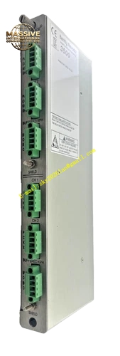
Description
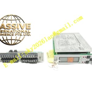
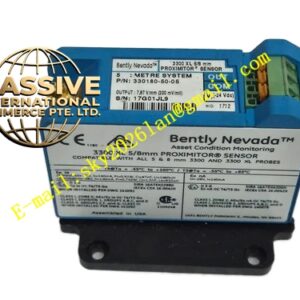
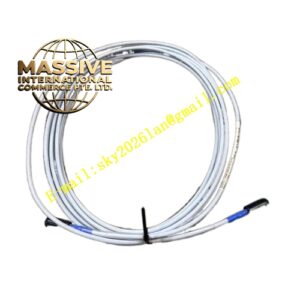
Bently 135462‑01 (190662‑13)
- Key Features: High‑bandwidth matched‑impedance shielded‑cable assembly; low signal‑distortion for high‑speed dynamic‑vibration‑data transmission; metal‑shell locking‑connectors; plug‑in rack‑mount I/O termination‑module; full‑mechanical‑locking‑structure preventing connector‑loosening; consistent impedance‑matching for transient‑signal transmission.
- Technical Specifications & Performance Parameters
- I/O module operating temperature: 0 ℃ ~ +60 ℃
- Cable operating temperature: ‑51 ℃ ~ +85 ℃
- Storage temperature: ‑40 ℃ ~ +90 ℃
- Nominal cable impedance: 120 Ω
- Weight: 0.45 kg total assembly
- Material Composition: FR‑4 multilayer printed circuit‑board for I/O unit; tin‑plated copper screw‑terminal blocks; high‑purity multi‑pair twisted‑copper conductors; full‑coverage copper‑braided shielding‑layer; FEP fluoropolymer insulation‑material; nickel‑plated metal‑shell D‑sub connectors with locking‑screws.
- Structural Features: Plug‑in rack‑mount I/O module form‑factor; front‑facing screw‑type field‑wiring terminals; rear‑side gold‑plated edge‑connector for rack‑back‑plane mating; factory‑integrated high‑speed transient‑data‑cable with metal‑locking‑D‑sub connectors on both ends; reinforced strain‑relief structure at cable‑connector transition sections.
- Working Principle: High‑speed transient‑diagnostic‑data generated by 3500/20 transient‑data‑interface module transfers through rack‑back‑plane bus into 135462‑01 I/O termination‑module. Signal passes onto factory‑matched 190662‑13 high‑speed shielded‑cable assembly. Cable transmits low‑distortion waveform, orbit and vector‑data stream to external diagnostic‑host‑equipment. Full‑coverage shielding suppresses external electromagnetic‑interference and guarantees dynamic‑signal fidelity.
- Application Scenarios: Physical‑signal‑transmission‑link for 3500/20 transient‑data‑interface module; high‑speed rotor‑dynamic‑diagnostic‑data delivery to System 1 workstation; connection with third‑party vibration‑analysis‑instruments; petrochemical‑and‑power‑plant turbomachinery‑fault‑diagnosis‑system wiring.
- Installation Requirements: Install I/O termination‑module directly behind corresponding 3500/20 transient‑data‑interface‑module; fully engage mechanical‑locking‑latch; tighten each screw‑terminal to factory‑specified torque‑value; attach D‑sub connectors on both cable‑ends and fully fasten locking‑screws; route high‑speed transient‑data‑cable inside independent cable‑tray away from high‑power‑cable‑routes; implement single‑end shielding‑grounding.
- Usage Notes: Never cut, splice or modify factory‑integrated 190662‑13 high‑speed‑cable assembly; strictly maintain minimum‑cable‑bending‑radius; avoid mechanical‑crushing‑damage on cable‑jacket; inspect D‑sub‑connector‑pin integrity during overhaul‑cycles; keep connector‑contact‑surfaces clean from oil‑mist, dust and moisture contamination.