Description
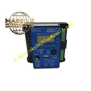
Bently 1900/65‑01‑02‑01‑00‑00
Technical Specifications:
- Input Channels: 4 dynamic transducer input channels; 4 temperature input channels
- Supported Dynamic‑Sensor Types: Eddy‑current proximity probes, 2‑wire /3‑wire velocity sensors, 2‑wire /3‑wire accelerometers
- Supported Temperature‑Sensor Types: Thermocouple Type E, J, K, T; 2‑wire /3‑wire RTD sensors
- Analog Recorder‑Output: Four‑channel configurable 4‑20 mA output
- Relay‑Output: Six configurable form‑C relay contact outputs
- Buffered Transducer‑Output: Dedicated buffered signal‑output per dynamic‑input‑channel
- Alarm‑Level Setting: Independent Alert and Danger threshold for each measurement‑variable
- Event‑Log Capacity: 200‑entry time‑stamped event history record
- Analog‑Digital Conversion: 24‑bit high‑resolution ADC, 25 kHz sampling bandwidth
- Communication Interface: RS232, RS485 serial port
- Mounting Method: Standard 19‑inch rack‑mount or panel‑mount installation
- Operating Temperature: ‑20 °C ~ +70 °C
- Storage Temperature: ‑30 °C ~ +90 °C
- Relative Humidity: 5‑95% RH non‑condensing
- Power‑Supply Requirement: 18‑30 VDC, nominal 24 VDC
- Power Consumption: Maximum 15 W Functional Features:
- Multi‑sensor compatible input‑channels, single monitor unit processes vibration, shaft‑displacement, rotational‑speed and multi‑point temperature‑monitoring signals simultaneously.
- Independent Alert and Danger alarm‑threshold configurable for every measurement variable; supports flexible voting‑logic configuration for relay‑trigger condition.
- Four‑channel isolated 4‑20 mA recorder‑output sends processed measurement‑values to external DCS and PLC control‑systems.
- Six programmable relay‑contact outputs support alarm‑annunciation and light‑duty machinery‑trip protection‑logic.
- Dedicated buffered transducer‑output for each dynamic‑channel, convenient for on‑site signal‑verification and portable‑diagnosis‑instrument connection.
- Built‑in 200‑entry timestamped event‑log records alarm trigger time, fault‑status and sensor‑loop fault‑events for post‑event analysis.
- Comprehensive sensor‑loop fault‑detection function, identifies probe open‑circuit, short‑circuit and sensor‑loop abnormal‑condition and marks Not‑OK status.
- Software‑driven full‑parameter‑configuration via dedicated 1900‑series configuration software, no hardware‑jumper adjustment on monitor body.
- Local LED indicator array displays channel health‑status, alarm‑state and module fault‑information for quick on‑site troubleshooting. Application Scenarios: Condition‑monitoring and light‑duty protection for packaged compressors, blowers, fans, process‑pumps and reciprocating‑machinery; OEM skid‑mount equipment matching; small‑and‑medium‑size unit reconstruction without large‑rack TSI hardware; industrial‑site local‑alarm monitoring points; machinery predictive‑maintenance data‑acquisition nodes. Performance Parameters: Measurement accuracy ±1% full‑scale; fast alarm‑response time; strong industrial‑electromagnetic‑interference‑resistance; high MTBF value for long‑term continuous‑operation. Material Composition: Metal‑alloy monitor housing; multi‑layer mixed‑signal PCB board; 24‑bit high‑resolution ADC chips; industrial‑grade digital signal‑processing microprocessor; electromagnetic‑isolation components; relay contact assemblies; screw‑type terminal‑block assemblies; LED indicator components. Structural Characteristics: Rectangular metal enclosure for panel‑mount or 19‑inch rack‑mount installation; front‑panel LED status‑indicator array; rear side terminal‑blocks for sensor‑input, power‑supply, relay‑output and communication‑wiring; housing printed with model‑number, electrical‑rating and serial‑identifier. Working Principle: Analog signals from field‑installed sensors feed into monitor input‑terminal‑blocks. On‑board circuit executes signal‑conditioning, filtering and high‑speed 24‑bit analog‑to‑digital conversion. Internal microprocessor runs configured measurement‑algorithms, calculates vibration amplitude, displacement, speed and temperature‑values. Calculated measurement‑values compare with preset Alert and Danger alarm‑thresholds. When measured‑value exceeds threshold or sensor‑loop fault occurs, corresponding relay‑output acts and event‑log records timestamped‑event. Processed measurement‑data converts to 4‑20 mA analog‑output for external control‑system. Measurement‑data and fault‑status transmit to upper‑host system through serial‑communication port. Installation Requirements:
- Mount monitor unit on standard 19‑inch rack or cabinet front‑panel according to dimension‑specification, fasten mounting screws completely.
- Strictly distinguish power‑supply terminals, sensor‑input terminals, relay‑output terminals and communication‑interface terminals, execute wiring complying with official wiring‑diagram.
- Provide regulated 24 VDC power‑supply within allowable voltage‑range for monitor unit.
- Separate sensor‑signal‑cable routing away from high‑current power‑cables to reduce electromagnetic‑interference coupling.
- Complete channel‑function‑definition, range‑setting and alarm‑threshold configuration by 1900‑configuration‑software, download all parameters into monitor internal memory before commissioning.
- Verify front‑panel LED indication status after power‑on, check sensor‑loop Not‑OK‑status and eliminate wiring‑fault. Usage Notes:
- Do not exceed maximum contact‑load rating of relay‑output terminals; adopt external intermediate‑relay for heavy‑load driving‑requirement.
- Do not open monitor housing; internal components cannot perform field‑repair, replace complete monitor unit upon hardware‑failure.
- Keep adequate ventilation‑clearance around monitor housing, avoid blocking heat‑dissipation area.
- Check terminal‑block screw‑tightness during equipment‑overhaul‑cycle to prevent signal‑fault caused by loose‑contact.
- Regularly export event‑log data for equipment‑fault‑trend‑analysis work.