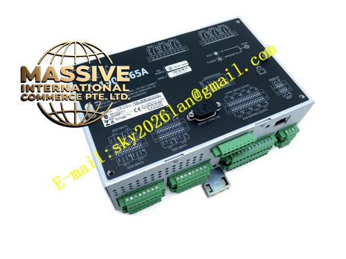
Description
Bently 21504‑000‑008‑10‑02
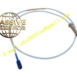
- Key Features: Standard 8 mm probe tip; 1.0 meter factory integrated coaxial cable; 3/4‑16 UNF mounting thread; epoxy hermetic sealing; stable linearity across full measuring range; compatible with all 7200 series proximitor modules.
- Technical Specifications & Performance Parameters
- Probe tip diameter: 8 mm
- Integral cable length: 1.0 m
- Linear measuring range: 0‑2.0 mm
- Nominal sensitivity: 7.87 V/mm
- Operating temperature range: ‑40 ℃ ~ +85 ℃
- Storage temperature: ‑55 ℃ ~ +125 ℃
- Frequency response: 0‑10 kHz
- Weight: 0.26 kg
- Thread specification: 3/4‑16 UNF‑2A
- Material Composition: Stainless steel threaded housing; precision wound copper sensing coil; high‑temperature PTFE insulated coaxial cable; metal shielding braid; epoxy resin sealing compound; microdot metal connector assembly.
- Structural Features: Cylindrical metal probe body; external mounting thread; rear‑exit 1.0 m integral coaxial cable; microdot connector at cable terminal; fully sealed coil cavity to resist moisture and dust ingress.
- Working Principle: High‑frequency excitation signal is transmitted from proximitor to probe coil. Eddy current forms on metallic shaft target surface. Coil impedance varies as physical gap changes. Impedance variation is converted into proportional DC voltage output inside proximitor unit.
- Application Scenarios: Compressor and turbine shaft‑vibration measurement; field installation positions requiring longer integral probe cable; legacy 7200 system spare‑parts replacement; petrochemical rotating‑machinery condition monitoring.
- Installation Requirements: Install probe into customized mounting bracket; adjust initial gap within linear working interval; fasten microdot connector securely; lay sensor cables separately away from high‑voltage power cables; perform single‑point grounding for cable shielding layer.
- Usage Notes: Probe tip must not suffer mechanical collision; maintain minimum bending radius for coaxial cable; avoid contamination on microdot connector contact pins; the whole transducer set must maintain total calibrated cable length defined by factory configuration.