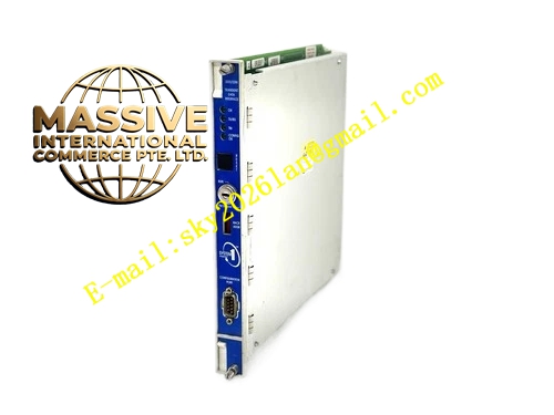
Description
Bently 330130‑04‑01‑00
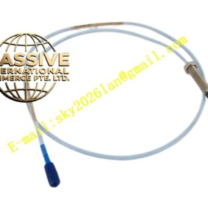
Technical Specifications: Cable Length: 4.0 m Nominal Impedance: 75 Ω Cable Construction: Triaxial coaxial structure Operating Temperature Range: ‑51 °C ~ +177 °C Minimum Static Bend Radius: 25.4 mm Connector Type: Click‑Loc gold‑plated self‑locking coaxial connector Maximum Tensile Load: 330 N Capacitance: 69.9 pF/m Net Weight: 560 g Compatible System: 3300 XL 8 mm proximity transducer system
Functional Features: Interlocked stainless‑steel armor resists cutting, squeezing and mechanical impact damage. Click‑Loc self‑locking connector prevents loosening under continuous high‑amplitude machine vibration, no special installation tools required. Full triaxial shielding structure suppresses industrial EMI and RFI interference efficiently. CableLoc strain‑relief molding sections at both cable ends absorb tensile stress and avoid inner conductor fracture. Factory pre‑matched electrical performance removes on‑site recalibration work. FEP insulation material maintains stable signal transmission under oil mist, dust and heavy‑pollution working conditions.
Application Scenarios: Shaft vibration, axial thrust displacement and Keyphasor phase reference signal transmission for steam turbines, centrifugal compressors, gearboxes, process pumps and generators. Deployed in thermal‑power, petrochemical and metallurgical sites where wiring paths face scratch, collision and squeeze risks.
Performance Parameters: Center Conductor DC Resistance: 0.88 Ω ±0.10 Ω Shield Conductor DC Resistance: 0.26 Ω ±0.06 Ω Connector Mating Cycle Life: More than 1000 insert‑extract cycles Maximum Operating Relative Humidity: 93 % non‑condensing
Material Composition: Inner Insulation Layer: Fluoroethylene‑Propylene (FEP) Signal Conductor: High‑purity silver‑plated copper Outer Armor Layer: AISI 302 interlocked stainless‑steel Connector Body: Gold‑plated brass alloy Sealing Gasket: Oil‑resistant high‑temperature fluororubber
Structural Features: 75‑Ω triaxial inner cable assembly wrapped by interlocked corrugated stainless‑steel armor. Both cable ends install Click‑Loc self‑locking circular connectors equipped with O‑ring sealing gaskets. CableLoc strain‑relief transition sections are molded at two terminals. The whole cable adopts integral manufacturing process without intermediate splice joints.
Working Principle: Passive signal‑transmission assembly without signal conversion or amplification function. It faithfully transmits high‑frequency impedance‑variation signals generated by probe coil, keeps complete impedance matching of the whole proximity measurement system, and preserves original amplitude and phase characteristics of gap‑voltage conversion output. The armor layer only provides mechanical protection and does not participate in signal transmission.
Installation Requirements: Strictly follow minimum static bend radius of 25.4 mm, forbid forced sharp bending. Reserve sufficient cable slack for thermal expansion and machine vibration displacement compensation. Route signal cable separately from high‑voltage power cables, never lay them inside one same conduit. Confirm full click‑loc engagement after connector mating operation. Implement single‑end grounding for cable shielding layer, double‑end grounding is strictly forbidden to prevent ground loop interference. Fasten cable with segmented metal clamps; cable assembly shall not bear mechanical weight of equipment.
Usage Notes: Do not cut, truncate or splice original factory cable on‑site. Total length of probe built‑in cable plus extension cable must strictly match Proximitor calibrated total‑system length. Only grip connector housing during disconnection operation, never pull cable body directly to separate connectors. Periodically inspect sealing gasket integrity to prevent oil and moisture invading into connector cavity. Avoid long‑term chemical‑medium immersion for connector parts.