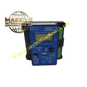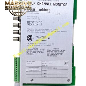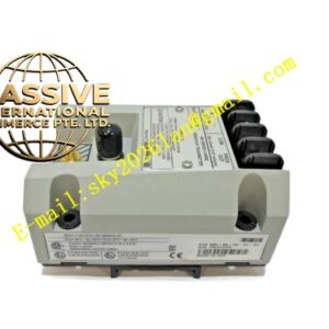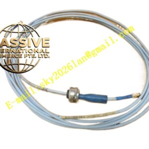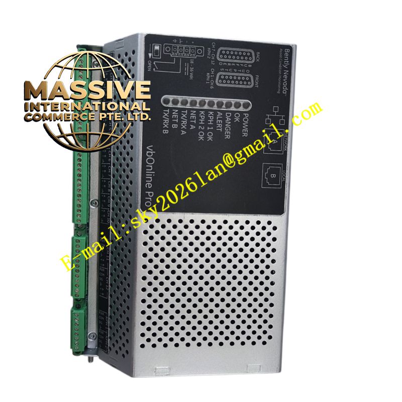
Description
Bently 330180-50-02
Technical Specifications
| Parameter Category | Specific Specification |
|---|---|
| Manufacturer | Bently Nevada (Baker Hughes) |
| Product Family | 3300 XL 8mm Proximity Transducer System |
| Product Type | Proximitor Sensor (Preamplifier) |
| Mounting Configuration | 50 = Compact rail mount with 3.5mm metric mounting thread |
| Agency Approval | 02 = No agency approval required |
| Measurement Range | 2.0 mm (80 mils) linear range |
| Output Sensitivity | 7.87 V/mm (200 mV/mil) |
| Electrical Zero | -10.0 VDC at 0.25mm (10 mils) gap |
| Frequency Response | 0 to 10 kHz (-3dB) |
| Power Supply | -17.5 to -26 VDC, typically -24 VDC |
| Supply Current | 12 mA typical |
| Output Impedance | 50 ohms |
| Target Material | Calibrated for AISI 4140 steel as standard |
| Operating Temperature | -35°C to +65°C (-31°F to +149°F) |
| Storage Temperature | -51°C to +100°C (-60°F to +212°F) |
| Relative Humidity | 100% non-condensing |
| Dimensions | Approximately 75 x 35 x 25 mm |
| Weight | Approximately 150 g |
Key Features
- Compact Rail Mount Design: Features a 3.5mm metric mounting thread for compact DIN rail installation, saving panel space and simplifying mounting
- High Radio Frequency Immunity: The 3300 XL Proximitor is highly immune to radio frequency interference, reducing installation complexity and eliminating need for separate shielding
- Electrical Isolation: Both rail mount and traditional panel mount bases are electrically isolating, eliminating the need for separate insulating boards
- Full Interchangeability: All 3300 XL 8mm system components (probe, extension cable, Proximitor) are fully interchangeable without individual matching or bench calibration
- API 670 Compliance: The complete 3300 XL 8mm system meets API 670 Standard (4th Edition) requirements for mechanical configuration, linear range, accuracy, and temperature stability
- Backward Compatibility: All 3300 XL 8mm components are backward compatible with non-XL 3300 series 5mm and 8mm sensor system components
Application Scenarios
- Steam turbine vibration monitoring: Measures shaft radial vibration, axial position, and differential expansion in power generation turbines
- Gas turbine condition monitoring: Monitors compressor and turbine shaft vibration and thrust bearing position
- Centrifugal compressor protection: Measures shaft vibration and axial displacement for machinery protection systems
- Pump and motor monitoring: Monitors bearing housing vibration and shaft position in critical process pumps and motors
- Generator condition assessment: Measures air gap, shaft vibration, and bearing condition in large generators
- Paper machine roll monitoring: Measures roll runout and bearing condition in paper manufacturing equipment
Performance Parameters The Proximitor provides a linear output range of 2.0 mm (80 mils) with excellent linearity of ±0.025 mm (±1.0 mil) over the full range. The incremental scale factor (ISF) is 7.87 V/mm (200 mV/mil) with tolerance of ±0.25 V/mm (±6.3 mV/mil). The average scale factor (ASF) is maintained within ±1.0% of 7.87 V/mm. The system accuracy is within ±0.025 mm (±1.0 mil) when calibrated to AISI 4140 steel target. The frequency response extends from DC to 10 kHz (-3dB), capturing all relevant vibration frequencies in rotating machinery.
Material Composition The Proximitor enclosure is constructed from aluminum with anodized finish for corrosion resistance. The mounting base is made from electrically insulating composite material. Internal electronic components include precision operational amplifiers, RF demodulation circuits, and filtering networks. The PCB is FR-4 epoxy glass fiber with surface-mount components. Connectors are gold-plated brass with high-cycle durability. The unit is fully encapsulated for environmental protection.
Structural Characteristics The Proximitor features a compact rectangular enclosure with the RF connector on one end and the signal output connector on the opposite end. The compact rail mount base includes a 3.5mm metric threaded stud for mounting to standard rails or brackets. The enclosure includes mounting holes for alternative panel mounting. Internal layout separates the RF input stage from the signal conditioning and output stage to minimize interference. The unit is fully potted for vibration and moisture resistance.
Working Principle The Proximitor receives a high-frequency RF signal (typically 1-2 MHz) from the probe via the extension cable. This RF signal is amplitude-modulated by the eddy current losses in the conductive target material as the probe-to-target gap changes. The Proximitor demodulates this RF signal using a precision detector circuit, filters the resulting signal to remove RF components, and amplifies the DC voltage proportional to gap distance. The output is a negative DC voltage that increases in magnitude as the probe approaches the target (smaller gap). The output is calibrated to be -10.0 VDC at the recommended probe mounting gap of 0.25mm (10 mils) from the target.
Installation Requirements
- Mount the Proximitor on a vibration-free surface using the compact rail mount base or panel mount screws
- Ensure proper electrical isolation from ground; the mounting base provides this isolation
- Connect the probe/extension cable to the RF input connector, ensuring proper torque on the connector nut
- Connect the output to the monitoring system using shielded cable, grounding the shield at the monitoring system end only
- Connect -24 VDC power supply to the power input terminals, observing correct polarity
- Maintain minimum 25 mm clearance from other electronic devices to prevent RF interference
- Install in an enclosure with minimum IP54 rating if used in dusty or wet environments
- Verify proper grounding of the monitoring system to ensure accurate measurements
Usage Precautions
- Never apply power without the probe connected; the Proximitor requires the probe as part of its tuned circuit
- Do not exceed the supply voltage range of -17.5 to -26 VDC; overvoltage will damage internal electronics
- Ensure the target material matches the calibration material (AISI 4140 steel standard); different materials require recalibration
- Keep the probe cable away from high-voltage power cables; maintain minimum 300 mm separation
- Do not kink or sharply bend the probe cable; minimum bend radius is 25 mm
- Check connector tightness periodically; loose connections cause intermittent readings
- Replace the unit if output drifts beyond ±10% of calibrated value
- Store in original packaging with desiccant if not installed immediately
- Follow proper ESD precautions when handling the unit