Description
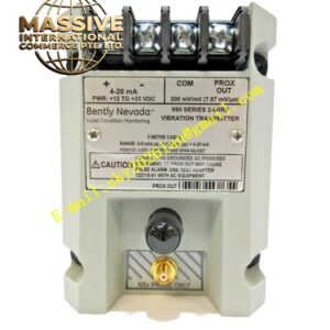
Bently 3500 42M
Technical Specifications
- Model Number: 3500/42M
- Channel Count: 4 independent channels
- Input Types: Proximity, Velocity, and Acceleration
- Power Consumption: 7.7 Watts
Key Features
- Dual Sensor Compatibility: Seamlessly integrates both non-contact proximity probes and seismic sensors in a single module.
- Paired Channel Programming: Channels are programmed in pairs (1&2, 3&4), allowing simultaneous execution of different monitoring functions.
- Advanced Signal Processing: Includes built-in digital filters for gap, direct, 1X, 2X, and non-1X vibration analysis.
- 4-20 mA Outputs: Provides independent, buffered analog outputs for each channel for external trending.
Application Scenarios
Extensively used in steam turbines, gas turbines, and large compressors to monitor absolute shaft vibration, casing vibration, axial displacement, and eccentricity.
Performance Parameters
- Resolution: 24-bit ADC for high-precision analog signal measurement
- Frequency Response: Up to 1 kHz (60,000 cpm) depending on configuration
Material Composition
Industrial-grade electronics housed in a ruggedized, flame-retardant enclosure with conformal coating for harsh environment protection.
Structural Characteristics
Standard full-height 3500 module form factor. Features front-panel BNC connectors for sensor inputs and comprehensive LED status indicators for OK, TX/RX, and Bypass states.
Working Principle
The module conditions the raw analog signals from the sensors, separates static (DC) and dynamic (AC) components, and continuously compares the processed values against user-programmable Alert and Danger setpoints to trigger protective relays.
Installation Requirements
Install in any available slot to the right of the Transient Data Interface (TDI) module. Use shielded coaxial cables for proximity probes and twisted-pair shielded cables for seismic sensors.
Usage Precautions
Ensure the correct sensor sensitivity is configured in the software. Verify that the paired channel logic matches the physical sensor installation to prevent erroneous machine trips.