Description
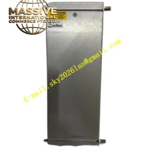
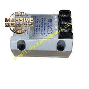
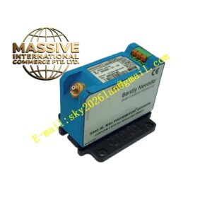
Bently 3500/50‑01‑00‑01 133388‑02
Technical Specifications Number of input channels: 2 independent input channels Compatible transducer: keyphasor eddy‑current proximity probe, magnetic pickup sensor Input signal amplitude range: 0.2 Vpp ~ 100 Vpp Speed measurement range: 0.1 RPM ~ 100000 RPM Trigger edge: configurable rising‑edge or falling‑edge trigger Measurement accuracy: ±1 RPM Power consumption: 7 W typical value, maximum 8.5 W Operating temperature: ‑40 ℃ ~ +70 ℃ Storage temperature: ‑40 ℃ ~ +85 ℃ Relative humidity: 5%‑95% RH, non‑condensing Shock resistance: 50 g peak value Vibration resistance: 10‑2000 Hz, 10 g peak value Backplane communication: 3500 proprietary system bus Module dimension: 241.3 mm × 24.4 mm × 241.8 mm Weight: 0.88 kg Compliance standard: API‑670, CE certification
Functional Features Two independent tachometer input channels. Supports rotating‑speed measurement, zero‑speed detection, reverse‑rotation identification and keyphasor phase reference output. Programmable trigger edge and number of target teeth. Dual‑level programmable Alert and Danger overspeed alarm setpoints, configurable alarm hysteresis and delay time. Zero‑speed alarm and reverse‑rotation alarm function can be enabled or disabled. Front‑panel LED indicators show channel health status, alarm trigger status and module running state. Buffered raw pulse‑signal output for external test instrument. Supports simplex, dual redundant and TMR triple‑modular‑redundant working modes. All measurement parameters and alarm thresholds downloaded from 3500 configuration software. Upload real‑time speed value and phase‑reference data to System‑1 diagnostic software. Output alarm logic to 3500 series relay modules for machinery protection. External termination version uses rear terminal‑block wiring without internal safety‑barrier circuit. Hot‑swap supported under normal rack power supply. This module cannot be used for emergency overspeed trip protection.
Application Scenarios Rotating‑speed monitoring and overspeed alarm for steam turbine and gas turbine. Keyphasor phase reference signal supply for vibration spectrum analysis of rotating machinery. Zero‑speed interlock protection for large centrifugal compressors. Reverse‑rotation detection for fan and pump unit. Speed monitoring for turbo‑generator set and hydro‑generator unit. Speed‑related condition monitoring for power plant and petrochemical non‑hazardous‑area rotating equipment. Installed in 3500 rack cooperating with vibration‑monitor module, communication module and relay module.
Performance Parameters Maximum input pulse frequency: 20 kHz Alarm response delay: less than 400 ms Phase‑reference output precision: ±1 degree Channel‑to‑channel crosstalk: less than 0.1% full scale MTBF value: more than 340000 hours under normal industrial environment
Material Composition Front panel: blue coated metal panel with silk‑screen text and LED indicator window. Main circuit board: multi‑layer FR‑4 high‑temperature resistant printed circuit board. Electronic components: pulse signal conditioning circuit, high‑speed counter chip, FPGA digital‑processing unit. Module housing: aluminum alloy electromagnetic shielding shell. Locking mechanism: stainless steel rack insertion latches. Connector: gold‑plated backplane connector and gold‑plated external‑termination terminal block.
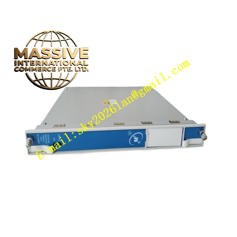
Structural Features Standard single‑slot plug‑in module for 3500 instrument rack. Front‑panel LED status‑indicator group and pull‑out latch mechanism. Rear gold‑plated multi‑pin backplane connector for power‑supply and system‑bus communication. External termination version routes tachometer‑sensor wiring to rear terminal block, no internal barrier circuit. Internal metal‑shielding shell isolates pulse‑signal processing zone and digital‑logic zone.
Working Principle Pulse signal generated by keyphasor probe or magnetic pickup enters channel signal‑conditioning circuit. Analog pulse signal is shaped into square‑wave digital pulse. High‑speed counter unit counts pulse number within fixed time window. Rotating‑speed value is calculated according to configured target‑tooth quantity. Phase‑reference signal is generated according to trigger edge setting. Measured speed value compares with pre‑programmed Alert and Danger overspeed thresholds. Zero‑speed logic judges whether pulse signal disappears within set time window. Reverse‑rotation logic judges pulse sequence of dual‑channel input. Alarm flag is generated when alarm condition is satisfied and transmitted to system bus and relay module. Real‑time speed and phase‑reference data is uploaded through rack backplane bus to rack‑interface module for upper‑level diagnostic‑software access. Buffered raw pulse‑signal is output for external test equipment.
Installation Requirements Insert module into designated slot of 3500 standard instrument rack, tighten front‑panel latches to guarantee reliable backplane‑connector contact. Connect keyphasor probe or magnetic‑pickup sensor cables to rear external‑termination terminal block strictly following terminal definition. Must cooperate with 3500/20 rack‑interface module for parameter‑configuration download. Ensure rack redundant‑power‑supply works normally. Maintain 20 mm ventilation clearance above and below rack cabinet. Tachometer‑signal cable shall keep more than 30 cm distance from high‑power power‑cable to avoid electromagnetic interference. Complete target‑tooth number, trigger‑edge and alarm‑threshold configuration by 3500 configuration software after hardware installation. Verify channel OK LED‑indicator light after power‑on.