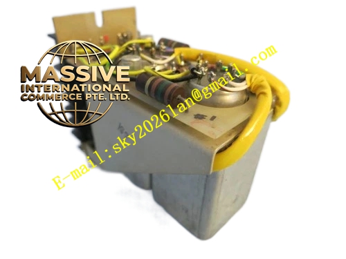
Description
Bently Nevada 131170-01
Technical Specifications:
- Product Series: 3500 Machinery Protection System
- Component Type: I/O Module Cable Assembly
- Part Number: 131170-01
- Function: Interconnection between monitor modules and I/O modules
Functional Features:
- Provides reliable electrical interconnection between 3500 front modules and rear I/O modules
- Ensures signal integrity for analog sensor signals and digital communication
- Designed for the specific pin-out and electrical requirements of 3500 system modules
- Supports the full range of 3500 monitor and I/O module combinations
Application Scenarios:
- 3500 rack assembly and maintenance
- Replacement of damaged or degraded I/O interconnection cables
- System upgrades requiring cable replacement
- Field service and troubleshooting of 3500 rack connections
Performance Parameters:
- Signal Type: Analog and digital signals compatible with 3500 system requirements
- Compatibility: 3500 series monitor and I/O modules
Material Composition:
- Shielded cable assembly with industrial-grade connectors
- Designed for long-term reliability in industrial environments
Structural Features:
- Pre-assembled cable with connectors matched to 3500 module interfaces
- Compact form factor for installation within the rack
Working Principle: The cable assembly carries analog sensor signals, digital status signals, and power between the front monitor cards and the rear I/O modules through the 3500 backplane connection. It ensures that the electrical characteristics of the signal path meet the system requirements for accurate measurement and reliable communication.
Installation Requirements:
- Connect between the appropriate front module and rear I/O module positions
- Ensure connectors are fully seated and locked
- Route cables to avoid interference with other rack components
Usage Precautions:
- Handle the cable assembly carefully to avoid damaging the connectors
- Verify correct cable orientation before insertion
- Do not bend the cable beyond its minimum bending radius
- Replace the cable if connector pins show signs of damage or corrosion