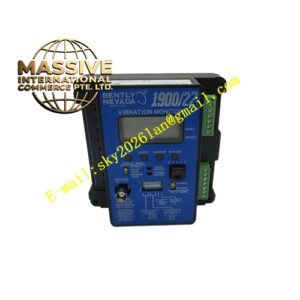
Description
Bently Nevada 3300/16-01-02-00-00-00-00
Technical Specifications
| Parameter | Specification |
|---|---|
| Channels | Two independent channels |
| Input Signals | Proximity probe/Proximitor systems |
| Input Impedance | 10 kΩ |
| Sensitivity | 100 mV/mil (4 V/mm) or 200 mV/mil (8 V/mm), jumper-selectable |
| Full-Scale Range | 0–5 mils peak-to-peak (configuration 01) |
| Frequency Range | 10 Hz to 1 kHz |
| Input Voltage | 24 VDC |
| Output Signal | 4–20 mA recorder output |
| Alarm Relays | Epoxy-sealed (configuration 01) |
| Operating Temperature | 0°C to +65°C |
| Storage Temperature | -40°C to +85°C |
| Weight | 1.0 kg |
| Dimensions | 2.5 cm × 25.7 cm × 24 cm |
| Origin | USA |
Functional Features
- Continuously monitors two independent channels of radial vibration
- Measures average shaft position (gap) for bearing condition assessment
- Provides digitally adjustable alarm setpoints for each channel
- Includes front-panel LCD display for direct reading of vibration levels
- Features LED indicators for OK, Alert, Danger, and Bypass status
- Offers recorder outputs for trending and data acquisition systems
- Supports trip multiply function for machinery startup protection
- Stores alarm configurations in nonvolatile memory
- Performs continuous self-diagnostics and transducer OK checking
Structural Characteristics The monitor consists of a main circuit board, an optional expander board, a front panel assembly with 83 mm vertical bargraph LCD, and a sheet metal enclosure. The front panel includes constant-ON green OK LEDs per channel, independent red Alert and Danger LEDs, red Bypass LEDs, and a system OK indicator. The rear panel provides terminal blocks for field wiring, coaxial connectors for buffered transducer outputs, and relay contact terminals. The module is conformal coated for environmental protection in harsh industrial atmospheres.
Working Principle The monitor receives eddy-current proximity probe signals representing shaft-to-probe distance variations. The signal conditioning circuit extracts both DC (gap) and AC (vibration) components from each channel. The DC component indicates average shaft position within the bearing, while the AC component is filtered, amplified, and measured for peak-to-peak amplitude. The microprocessor compares these values against user-programmed alarm setpoints, activates relays when thresholds are exceeded, and drives the front-panel display and LEDs. The unit continuously verifies transducer integrity by monitoring signal levels within expected ranges.
Installation Requirements
- Mount in standard 3300/05 series rack
- Use shielded triad cable for all transducer connections
- Route transducer cables separately from AC power cables
- Connect cable shields to single-point ground
- Verify probe gap voltage near -10 VDC for 8 mm probes at installation
- Configure sensitivity jumpers to match transducer scale factor
- Program alarm setpoints through front-panel switches after installation
Application Scenarios
- Fluid-film bearing machine vibration monitoring
- Steam turbine radial vibration protection
- Gas compressor bearing condition monitoring
- Generator shaft vibration supervision
- Refinery critical pump monitoring
- Large motor bearing health assessment