Description
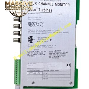
Bently Nevada 3300/47
Technical Specifications
| Parameter | Specification |
|---|---|
| Input | Two proximity probe transducer signals |
| Input Impedance | 10 kΩ |
| Signal Scale Factor | 100 mV/mil (4 V/mm), 20 mV/mil (0.787 V/mm), or 10 mV/mil (3.92 V/mm), jumper-selectable |
| Accuracy | Within ±0.33% of full-scale typical, ±1% maximum at +25°C |
| Power Consumption | 1.5 watts nominal |
| Recorder Output | 4–20 mA, 0 to -10 Vdc, or 1–5 Vdc |
| Recorder Accuracy | ±0.7% of signal, ±0.09 mA offset for 4–20 mA |
| Output Impedance | 100 Ω |
| Alarm Setpoints | Four per channel (two over, two under) |
| Display Resolution | Within ±1.6% of full-scale |
| Operating Temperature | 0°C to +65°C |
| Storage Temperature | -40°C to +85°C |
| Relative Humidity | 95% noncondensing |
| Origin | USA |
Functional Features
- Provides extended differential expansion range using complementary probe arrangement
- Achieves up to double the linear range of a single transducer
- Displays both magnitude and direction of differential expansion
- Features four programmable alarm setpoints per channel
- Offers multiple recorder output options (current or voltage)
- Includes buffered transducer outputs for external analysis
- Features front-panel LCD display with 63 segments
- Provides LED indicators for OK, Alert, Danger, and Bypass status
- Supports latching and non-latching alarm modes
- Performs continuous self-diagnostics and cyclic testing
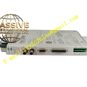
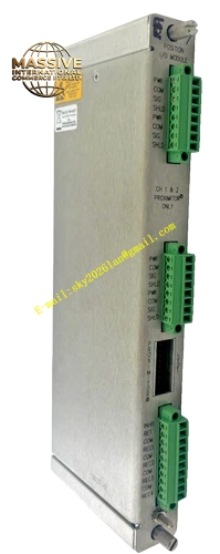
Structural Characteristics The monitor is constructed as a standard 3300 rack module with a front panel containing an 83 mm vertical bargraph LCD, green OK LEDs per channel, red Alert and Danger LEDs, and red Bypass LEDs. The rear panel provides terminal blocks for field wiring, coaxial connectors for buffered transducer outputs, and relay contact terminals. The internal circuitry includes dual-channel signal conditioning, automatic range switching logic, and microprocessor-based measurement and alarm processing.
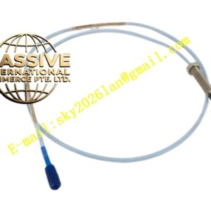
Working Principle Two proximity probes are mounted on opposite sides of a rotor collar, facing each other. As the rotor thermally expands, the collar moves axially. When the collar moves away from one probe (increasing gap), it moves toward the other probe (decreasing gap). Each probe operates within its linear range for approximately half of the total travel. The monitor automatically selects the valid signal from the probe with the best linearity and combines the two measurements into a seamless, continuous output. This complementary technique effectively doubles the measurable range without requiring specialty large-range transducers.
Installation Requirements
- Mount two proximity probes facing opposite sides of rotor collar
- Ensure probes are aligned axially and radially for proper coverage
- Use shielded coaxial cable for all transducer connections
- Program upscale direction to match probe orientation
- Set alarm thresholds based on combined measurement range
- Verify smooth transition between probe ranges during commissioning
- Test automatic probe selection logic over full travel range
Application Scenarios
- Extremely large steam turbines with massive thermal growth
- Heavy-duty gas turbines with significant differential expansion
- Large generators exceeding standard probe linear ranges
- Industrial machinery with limited transducer mounting options
- Refinery critical equipment requiring extended range monitoring
- Power plant turbine supervisory instrumentation upgrades