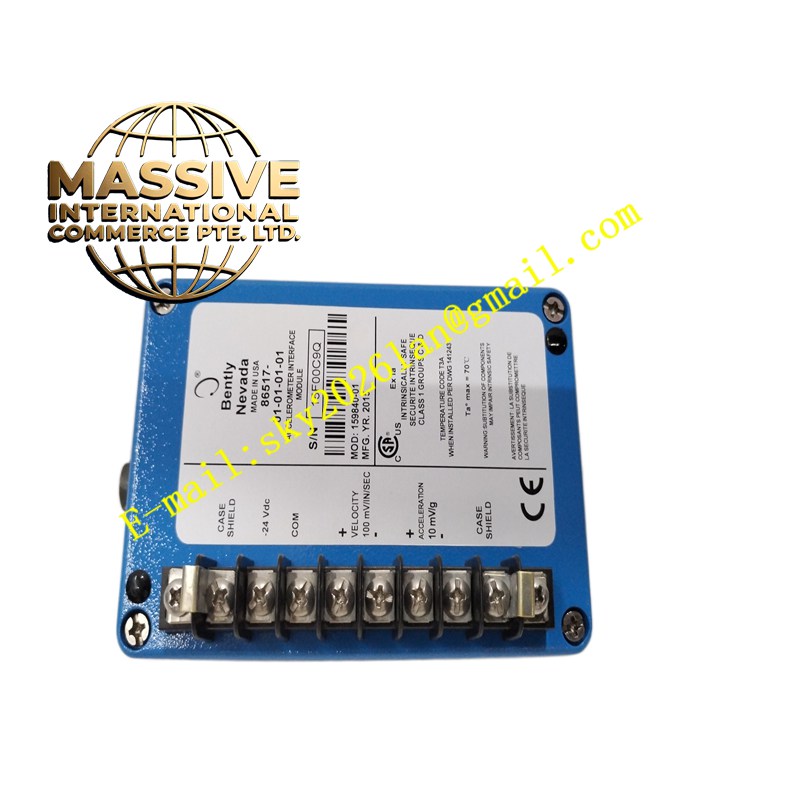
Description
Bently Nevada 330103-00-14-10-01-00
Technical Specifications:
- Probe Diameter: 8 mm
- Mounting Thread: M10×1 metric thread
- Sensitivity: 7.87 V/mm (200 mV/mil)
- Linear Range: 2 mm (0.25 mm to 2.3 mm)
- Frequency Response: 0 to 10 kHz
- Recommended Gap Setting: 1.27 mm (50 mils), approximately -10 Vdc
- Operating Temperature (Probe Tip): -51°C to +177°C
- Connector Type: Code -01 connector variant
- Agency Approvals: None (standard industrial, -00 suffix)
- Compliance: API 670 standard
Functional Features:
- Non-contact eddy current measurement for shaft vibration and displacement
- Multi-parameter capability: vibration, displacement, keyphasor, speed, eccentricity
- Interchangeable within the 3300 XL 8mm system
- Compatible with 3500, 2300/20, and 1900/65A monitoring systems
- Standard industrial certification suitable for non-hazardous areas
Application Scenarios:
- Electric motors and generators in general industrial plants
- Centrifugal pumps and fans
- Gearboxes and speed reducers
- Compressors and blowers in non-hazardous environments
- Water treatment and HVAC rotating equipment
- General-purpose machinery condition monitoring
Performance Parameters:
- Sensitivity: 7.87 V/mm ±5% (5m system)
- Linearity: ±1% full scale
- Resolution: 0.1 μm
- Frequency Response: DC to 10 kHz
Material Composition:
- Probe Housing: AISI 303/304 stainless steel
- Probe Tip: PPS engineering plastic with ferrite core
- Cable: FEP-insulated coaxial cable
- Connectors: Gold-plated copper coaxial
Structural Features: Cylindrical 8mm probe body with M10×1 threaded mounting. The -14 code indicates a specific probe body length. The -10 code indicates the cable length. The -01 connector type provides the interface to the extension cable.
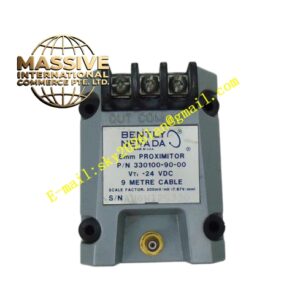
Working Principle: The probe operates on the eddy current principle. A high-frequency oscillating coil in the probe tip generates an alternating magnetic field. When positioned near a conductive target, eddy currents are induced on the target surface, creating a counter magnetic field. The interaction changes the probe coil impedance proportionally to the gap distance. The Proximitor electronics convert this impedance change into a linear voltage output.
Installation Requirements:
- Mount in M10×1 threaded bracket with 1.7 to 2.3 N·m torque
- Ensure perpendicular alignment to the shaft surface
- Total system cable length must be 5.0 m or 9.0 m
- Connect to 3300 XL Proximitor via extension cable
- Adjust gap to -10.0 Vdc ± 0.2 Vdc
- Single-point shield grounding
- Route signal cables away from EMI sources
Usage Notes:
- The -00 suffix indicates no hazardous area certification; install only in non-hazardous (safe area) locations
- Target material must match Proximitor calibration
- Target surface must be clean and smooth (roughness better than 1.6 μm)
- Perform gap adjustment with the machine at rest
- Verify cable and connector integrity during maintenance