Description
Bently Nevada 330104‑00‑25‑10‑02‑00
Technical Specifications: Probe tip diameter: 8 mm Built‑in cable length: 1.0 m Mounting thread: M10×1 metric thread Scale factor: 7.87 V/mm Linear measuring range: 0.25 mm‑2.3 mm Recommended working gap: 1.27 mm Frequency response: DC‑10 kHz Cable rating: standard‑temperature grade
Functional Features: Non‑contact measuring principle eliminates mechanical‑friction loss Interchangeable with other 3300 XL 8 mm‑series probes, extension cables and proximitor sensors Low temperature‑drift characteristic Excellent anti‑electromagnetic‑interference performance Simultaneous output of static‑position and dynamic‑vibration measuring signals
Application Scenarios: Radial shaft vibration, thrust axial‑displacement and Keyphasor rotational‑signal measurement for steam turbines, centrifugal compressors, fans, generators and process pumps. Widely deployed inside power‑plant, petrochemical and metallurgy machinery‑protection systems.
Performance Parameters: Probe tip operating temperature: −52 °C ~ +177 °C Standard‑temperature cable operating temperature: −52 °C ~ +177 °C Probe coil resistance: 7.59 Ω ±0.5 Ω Maximum relative humidity: 93 % non‑condensing Scale‑factor tolerance: ±5 % across full linear measuring range
Material Composition: Probe tip: high‑temperature epoxy encapsulation Probe housing: 316 stainless steel Internal sensing coil: high‑temperature enameled copper wire Cable outer jacket: fluoropolymer insulating material Connector assembly: nickel‑plated alloy circular connector
Structural Features: Integrated probe‑cable assembly M10×1 male mounting thread Hermetically sealed probe‑tip unit Tri‑axial fully‑shielded signal cable Standard locking‑type miniature circular connector Compact mechanical outline adapting narrow‑diameter installation bore position
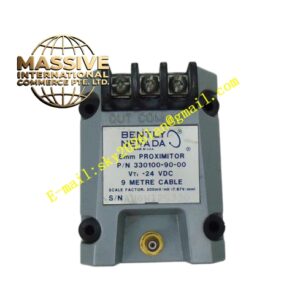
Working Principle: Eddy‑current effect governs operation. Probe internal coil generates high‑frequency alternating magnetic field and induces eddy currents on measured metal‑target surface. Gap‑distance change between probe tip and target alters probe‑coil impedance. Proximitor sensor converts impedance variation into analog DC‑voltage signal proportional to clearance distance.
Installation Requirements: Probe‑mounting axis must maintain perpendicular orientation to target metal surface Signal‑cable laying keeps adequate distance from high‑voltage power cables Minimum static cable bending radius: 25 mm Reserve proper cable slack for equipment thermal‑expansion movement Fully lock connector after wiring completion
Usage Notes: Factory‑integrated probe cable cannot be cut or spliced Avoid mechanical impact damage to probe tip during installation and overhaul Measured target surface must present exposed bare‑metal status without thick coating Operating temperature shall not exceed rated parameter limits Inspect connector locking state regularly during long‑term equipment running