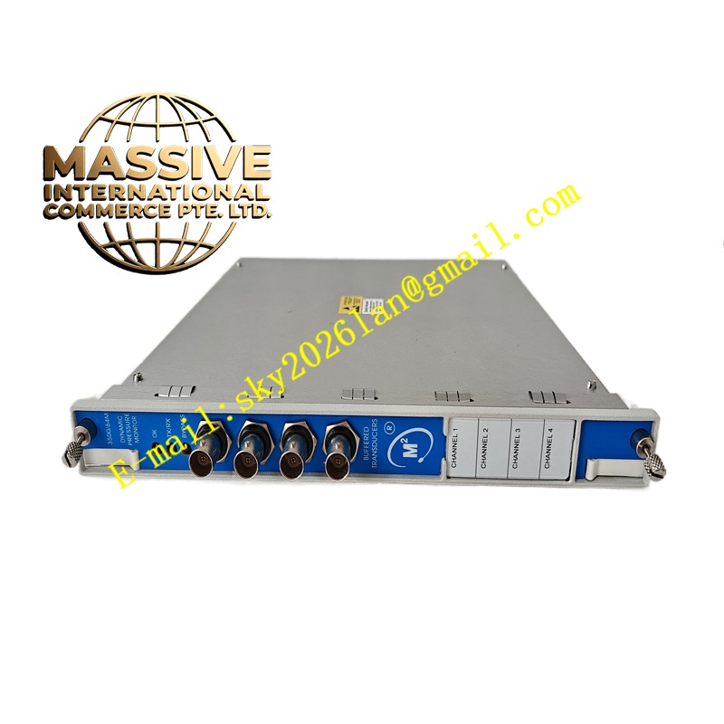
Description
Bently Nevada 3500/25-01-01-01
Technical Specifications:
- Module Type: Half-height, 2-channel
- Power Consumption: 3.2 watts typical
- Input Signal Range (Non-Isolated I/O): +0.8V to -21.0V
- Input Impedance: Minimum 21.8 kΩ
- Auto Threshold: Minimum trigger signal amplitude 2V peak-to-peak; minimum frequency 120 rpm (2 Hz)
- Manual Threshold: User-selectable 0 to 20 VDC; minimum trigger signal amplitude 500 mV peak-to-peak
- Hysteresis: 0.2 to 2.5V, user-selectable
- Buffered Output Impedance: 504 Ω maximum
- Sensor Power Supply: -24 VDC, maximum 40 mA per channel
- Operating Temperature: -30°C to +65°C (with non-isolated I/O module)
- Storage Temperature: -40°C to +85°C
- Humidity: 95% non-condensing
Functional Features:
- Receives signals from eddy current proximity probes or magnetic pickups
- Converts analog input to digital keyphasor pulses for shaft phase reference
- Provides two buffered keyphasor outputs accessible via front panel coaxial connectors and rear Euro-connector
- Automatic threshold detection with minimum 2V peak-to-peak trigger
- Manual threshold mode for user-defined trigger levels
- Records shaft speed from each keyphasor sensor for use by communication gateway and RIM modules
- Returns module and channel status to the rack
- Field-upgradeable firmware
- Generates once-per-revolution event signals from multiple-per-revolution inputs
- Fully backward-compatible with legacy 3500 Keyphasor module (PWA 125792-01)
Application Scenarios:
- Turbine Supervisory Instrumentation (TSI) systems requiring shaft phase reference
- Vibration vector measurement (1X amplitude and phase) in rotating machinery
- Compressor, pump, fan, and motor monitoring
- Systems requiring phase-synchronous data acquisition for orbit plots and Bode/Polar diagrams
- TMR (Triple Modular Redundancy) configurations for critical machinery protection
Performance Parameters:
- Channel count: 2 channels per module
- Maximum keyphasor signals per system: 4 (standard), 8 (paired configuration)
- Minimum detectable frequency: 120 rpm (2 Hz) with auto threshold
- Minimum detectable frequency: 1 rpm (0.017 Hz) with manual threshold
- Passive magnetic pickup minimum shaft speed: 200 rpm (3.3 Hz)
Material Composition:
- High-reliability electronic components on multi-layer PCB
- Metal module enclosure with conformal coating
- Gold-plated backplane edge connectors
- Coaxial connectors for buffered output
Structural Features:
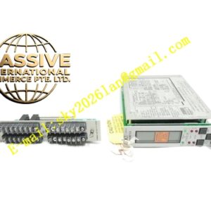
- Half-height module form factor (occupies one half-slot in the rack)
- Front panel with OK and TX/RX LED indicators, plus two coaxial buffered output connectors
- Rear I/O module (full-height) with internal terminal connections
- Plug-in design compatible with any of the 14 accessible rack slots
Working Principle:
The keyphasor module receives analog signals from proximity probes or magnetic pickups mounted near a shaft keyway or gear tooth. The module conditions the input signal, applies threshold detection and hysteresis filtering, and generates a clean digital pulse each time the shaft keyphasor mark passes the sensor. This digital keyphasor signal serves as a phase reference for all monitor modules in the rack, enabling vector measurements such as 1X amplitude and phase angle. The module also calculates and records shaft speed from the pulse frequency.