Description
Bently Nevada 3500/42M-07-00 (138708-01)
- Key Features: Four independent configurable measurement channels; supports proximity, velocity and acceleration transducer inputs; built‑in shaft‑absolute signal processing function; channel‑pair programming architecture, two groups of measurement tasks can run simultaneously; configurable Alert and Danger alarm thresholds for every measurement variable; circular‑acceptance‑region alarm logic; buffered short‑circuit‑protected transducer output ports; complete hot‑swap capability; multi‑color LED front‑panel status indicators; enhanced internal transducer cable fault diagnosis capability.
- Technical Specifications & Performance Parameters
- Input channel quantity: 4 configurable multi‑function channels
- Typical power consumption: 8.6 W
- Operating temperature: 0 ℃ ~ +60 ℃
- Storage temperature: ‑40 ℃ ~ +85 ℃
- Frequency response range: 4 Hz‑4000 Hz user‑programmable filter
- Measurement accuracy: ±1 % full‑scale maximum error
- Buffered output impedance: 300 Ω
- Weight: 0.52 kg
- Material Composition: High‑Tg FR‑4 multilayer industrial printed‑circuit board; mixed‑signal analog‑digital conversion chips; high‑frequency excitation circuit components for eddy‑current probes; gold‑plated back‑plane edge connector; metal front‑panel with multi‑color LED indicators; metal shielding can for sensitive analog signal circuits; reinforced glass‑filled nylon mechanical locking latch.
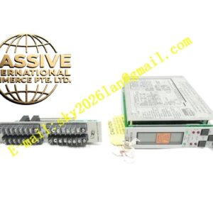
- Structural Features: Full‑height plug‑in rack‑module mechanical structure; front‑panel LED indicators display power‑supply status, channel signal health and alarm trigger status; rear‑side gold‑plated edge connector mates with 3500 rack back‑plane bus; field sensor wiring terminates to matched external I/O termination module; front‑panel coaxial buffered signal output connectors; mechanical latch locks module firmly inside rack slot.
- Working Principle: Module generates high‑frequency excitation signal for proximity probe system or completes signal conditioning for seismic velocity and acceleration sensors. Transducer feedback signal enters analog‑conditioning circuit, then converted into digital measured value through high‑precision A/D converter. Internal firmware computes radial vibration, thrust position, differential expansion, eccentricity, shaft‑absolute and other parameters. Real‑time measured values compare with user‑configured alarm setpoints. Alarm status flags transmit over rack back‑plane bus to relay modules and communication gateway modules.
- Application Scenarios: Combined relative shaft‑vibration and casing absolute‑vibration protection for steam‑turbine, gas‑turbine and centrifugal compressors; shaft‑absolute vibration monitoring for high‑speed rotating shafts; thrust bearing axial‑position and differential‑expansion measurement; petrochemical and power‑plant TSI racks requiring mixed proximity and seismic sensor signal acquisition.
- Installation Requirements: Insert full‑height monitor module into designated rack slot; fully engage mechanical locking latch; install matched external I/O termination module and complete field transducer wiring; configure transducer type, system total electrical length, filter parameters and alarm thresholds via 3500 rack configuration software; perform gap calibration and signal simulation test to verify measurement reading correctness.
- Usage Notes: Execute complete ESD static‑electric‑protection measures during module handling and replacement; strictly follow official maintenance workflow for hot‑swap operation; prohibit mismatch between configured transducer total electrical length and actual on‑site probe plus extension‑cable combined length; inspect front‑panel LED status during daily equipment inspection rounds; save complete rack‑configuration backup file after modifying any channel‑related parameters.