Description
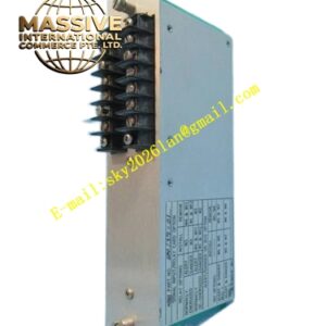
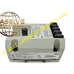
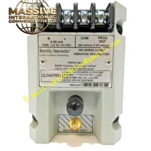
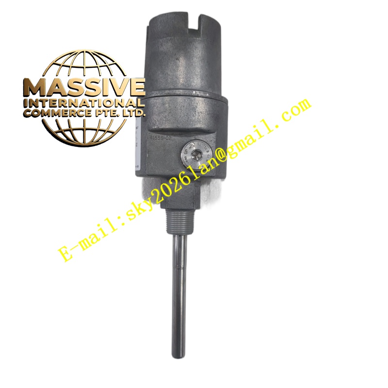
Bently Nevada 3500/46M
Technical Specifications
- Channels: 4 input channels
- Input Types: Proximity probes, seismic transducers, air gap sensors
- Input Impedance: approximately 10 kΩ on standard I/O
- Frequency Response (Direct): Low mode 0.1875 Hz to 343.75 Hz, High mode 0.75 Hz to 1375 Hz
- Measurement Accuracy: ±0.33% of full scale typical, ±1% maximum
- Power Consumption: approximately 7.7 watts typical
- Operating Temperature: -30°C to +65°C
- Storage Temperature: -40°C to +85°C
- Humidity Tolerance: 95% non-condensing
- Mounting: 3500 series rack slot
- Configuration: 3500 Rack Configuration Software
Functional Features
- Multimode input capability supporting proximity, velocity, and temperature sensors
- Advanced digital signal processing with configurable filtering
- User-programmable Alert and Danger alarm setpoints per channel
- Front panel status LEDs indicating OK, TX/RX communication, and Bypass conditions
- High channel density within a single module
- Seamless integration with the Bently Nevada 3500 Series platform
- Backward compatibility with existing 3500 rack architectures
Application Scenarios
- Hydro turbine generator vibration monitoring
- Pump and compressor protection systems
- Radial and axial vibration measurement on fluid-film bearing machines
- Shaft position, thrust, and differential expansion monitoring
- Shear-pin failure detection in hydroelectric equipment
- Integration with SCADA and DCS systems for centralized monitoring
Performance Parameters
- Linear range compliance with API 670 standards
- Fast response time for alarm condition detection
- Buffered transducer outputs with short-circuit protection
- Stable measurement accuracy across the full operating temperature range
- Low noise floor ensuring high-fidelity signal conditioning
Material Composition
- Front panel: Industrial-grade aluminum or coated steel
- Internal circuit boards: Multi-layer FR4 with surface-mount components
- Connectors: Gold-plated contacts for reliable signal transmission
- Housing: Ruggedized metal enclosure with corrosion-resistant finish
Structural Characteristics
- Standard 3500 series full-height or half-height module form factor
- Front-facing coaxial connectors for buffered output access
- Rear I/O module mating for signal termination
- LED indicator array for at-a-glance operational status
- Rack-mounted design with card guides and locking mechanism
Working Principle The monitor receives analog signals from field-installed sensors, amplifies and filters them through internal signal conditioning circuits, and converts the processed data into digital values. These values are continuously compared against configured alarm thresholds. When a measured parameter exceeds an Alert or Danger setpoint, the module activates corresponding relay outputs and communicates the status to the rack interface for upstream notification.
Installation Requirements
- Install only in a Bently Nevada 3500 series rack with compatible backplane
- Ensure proper mating with the corresponding I/O module
- Maintain adequate spacing for thermal dissipation
- Use shielded cables for all sensor connections with shield grounded at the rack end
- Verify firmware compatibility before commissioning
Usage Precautions
- Do not install or remove the module while rack power is applied
- Verify all sensor gap voltages are within linear range before enabling alarms
- Regularly verify alarm setpoints through the configuration software
- Keep the front panel connectors free from moisture and contamination
- Perform periodic channel verification tests to ensure measurement integrity