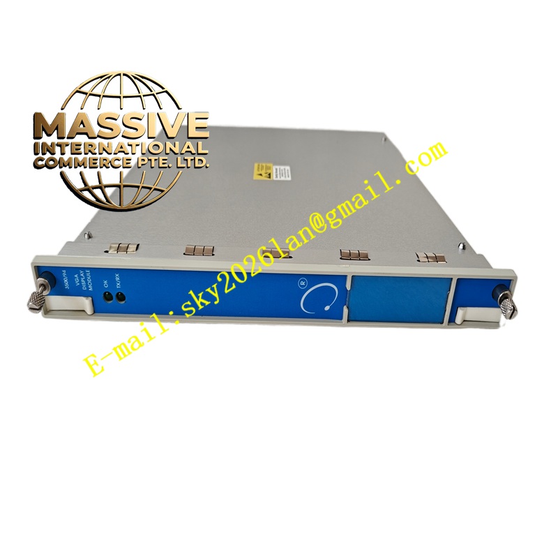
Description
Bently Nevada 9200-01-06-10-00
Technical Specifications:
| Parameter | Specification |
|---|---|
| Manufacturer | Bently Nevada |
| Series | 9200 Series |
| Product Type | Two-Wire Velocity Seismoprobe Transducer |
| Mounting Angle | 0 ±2.5 degrees |
| Minimum Operating Frequency | 4.5 Hz (270 cpm) |
| Mounting Base | Circular with M10X1 stud |
| Agency Approval | No approvals required |
| Sensitivity | 20 mV/mm/s (500 mV/in/s), ±5% when properly terminated and oriented at calibration angle |
| Calibration Load | 10 kΩ between terminals |
| Sensitivity Temperature Coefficient | 0.2% per degree Celsius |
| Frequency Response | 4.5 to 1000 Hz (270 to 60,000 cpm), +0, -3 dB typical |
| Dynamic Operating Range | 2.54 mm (0.100 in) peak-to-peak maximum displacement |
| Velocity Range | 25 mm/s (1 in/s) at +22°C at 100 Hz with 10 kΩ load |
| Coil Resistance | 1.25 kΩ ±5% |
| Locked Coil Inductance | 125 mH typical |
| Amplitude Linearity | ±5% from 0.01 to 5.0 in/s (0.254 to 127 mm/s) at 100 Hz |
| Shock Resistance | Withstands 50 g peak maximum acceleration along non-sensitive axis |
| Transverse Sensitivity | ±10% maximum of sensitive axis sensitivity at 100 Hz and 1.0 in/s |
| Output Signal Polarity | Pin A goes positive with respect to Pin B when transducer case velocity is towards connector |
| Maximum Lead Wire Length | 305 meters (1,000 feet) maximum between transducer and 3300 or 3500 Monitor |
Functional Features: The transducer provides a direct velocity output without requiring external integration electronics. This simplifies system architecture and improves signal reliability. The moving-coil design exhibits lower sensitivity to impact and impulsive excitation compared to solid-state velocity transducers that incorporate accelerometers with embedded integration electronics. The two-wire configuration reduces installation complexity and material costs. The circular M10X1 mounting base provides metric thread compatibility for international machinery standards.
Structural Characteristics: The transducer housing is constructed from anodized aluminum with a typical height of 102 mm and diameter of 41 mm. The circular mounting base features an M10X1 metric threaded stud for secure attachment. The housing material provides excellent resistance to corrosive industrial environments. The internal coil assembly is precision-wound and suspended in a carefully engineered magnetic circuit. The unit is sealed to resist dust and moisture penetration. Weight is approximately 300 grams typical for the 9200 model.
Working Principle: The transducer operates as an electrodynamic velocity sensor. When the machine surface to which the transducer is attached vibrates, the internal permanent magnet assembly moves relative to the suspended coil. This relative motion induces an electrical voltage in the coil according to Faraday’s law of electromagnetic induction. The magnitude of the induced voltage is directly proportional to the vibration velocity. The signal is extracted through two terminals and transmitted to the monitoring instrumentation.
Installation Requirements: Prepare a mounting surface with an M10X1 threaded hole or use an appropriate adapter plate. Ensure the transducer mounting axis is aligned with the desired measurement direction within ±2.5 degrees. Apply appropriate mounting torque to secure the transducer without damaging the threads. Use shielded twisted-pair cable for electrical connections to the monitoring system. Observe proper polarity as indicated by terminal markings. Maintain cable lengths within the specified maximum of 305 meters between the transducer and the monitoring system input.
Application Scenarios: Vibration monitoring on European and Asian-manufactured rotating equipment with metric mounting provisions, bearing housing vibration measurement on pumps and compressors, casing vibration monitoring on steam and gas turbines, structural vibration assessment on large motors and generators, and general machinery condition monitoring in industrial plants worldwide.
Usage Considerations: Verify metric thread compatibility before installation. The M10X1 stud requires careful engagement to prevent cross-threading. Do not operate the transducer in continuous temperatures exceeding +121°C. Ensure proper cable shield grounding at the monitoring system end only to prevent ground loop interference. The transducer requires no external excitation power. Verify that the monitoring system input impedance is approximately 10 kΩ for proper sensitivity calibration. Inspect mounting tightness during routine maintenance to ensure continued measurement accuracy.