Description
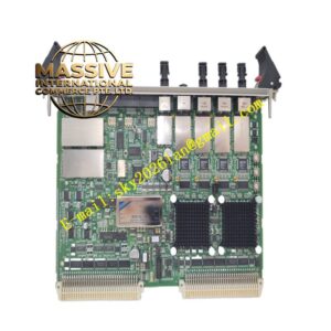
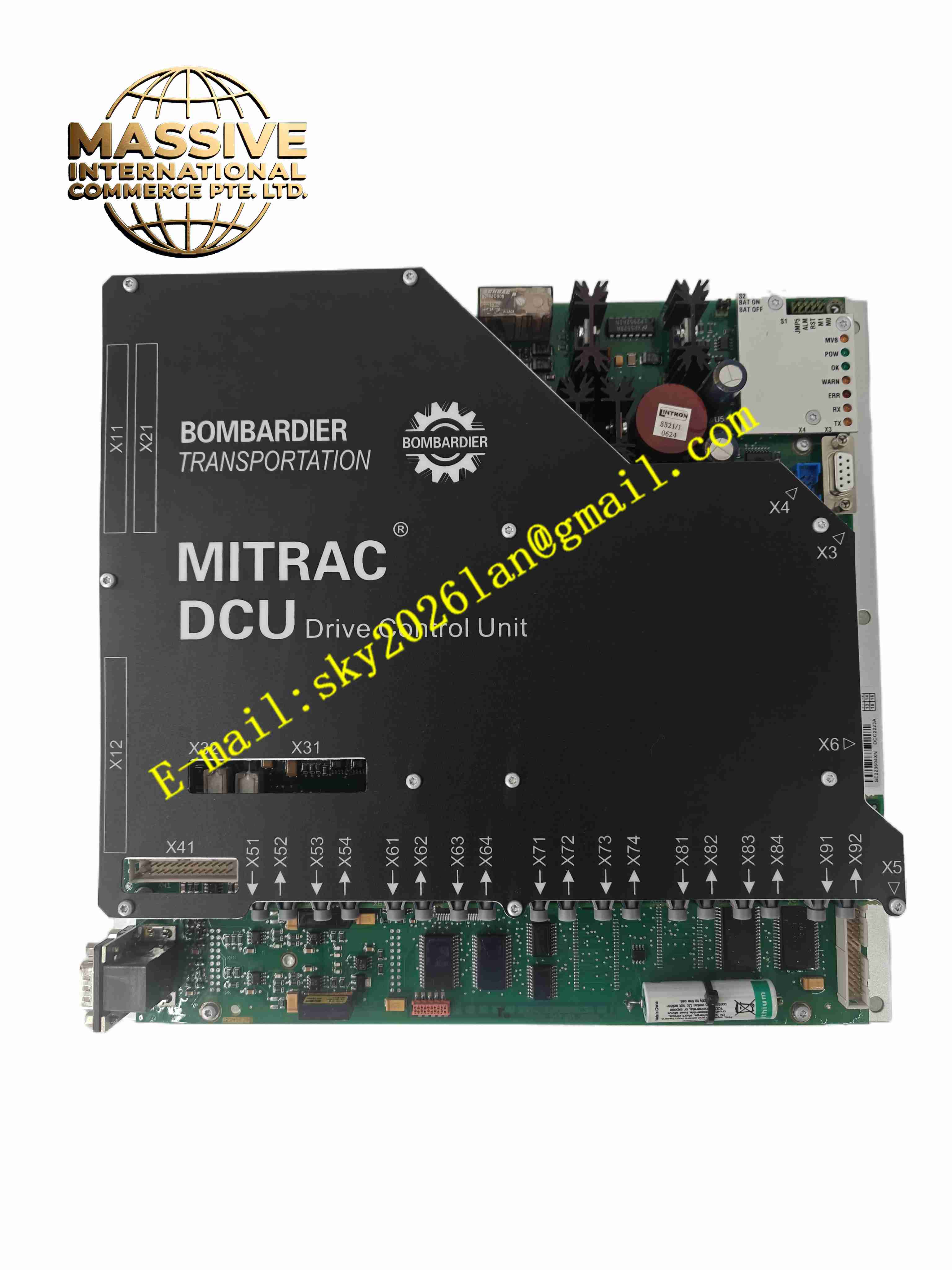
BOMBARDIER DCC2223A 3EST125-977
Technical Specifications Designed for rail vehicle on-board DC traction supply; multi-channel analogue and digital signal acquisition interfaces; optical fibre communication links for power converter gate signals; built-in hardware overcurrent, overvoltage and overtemperature protection; operating temperature range -40 °C to +85 °C; ruggedised PCB with conformal coating; rack-mounted vehicle chassis form factor; EMC compliance with railway rolling stock standards.
Functional Features Real-time vector control for traction motors; traction and electric brake torque closed-loop regulation; fault recording and event timestamp storage; safe pulse block function for power device protection; communication with vehicle control unit via train bus; diagnostic data upload for maintenance; speed and position signal processing from motor encoders.
Application Scenarios Metro train traction converter cabinets, light rail vehicle propulsion control, urban mass transit rolling stock retrofit and spare replacement.
Material Composition Aluminium alloy module housing for mechanical shock protection; FR4 multilayer PCB with acrylic conformal coating; industrial automotive-grade processors and memory chips; optical fibre transceivers; gold-plated heavy-duty rail-grade connectors; surge suppression and reverse polarity protection components.
Structural Characteristics Rugged enclosed chassis with vibration-resistant fasteners; front panel equipped with status LEDs and service connectors; rear multi-pin heavy-duty connectors for vehicle power and signal wiring; internal isolation between low-voltage control circuits and high-power traction signal circuits.
Working Principle The unit receives torque commands from the vehicle master controller and feedback signals from motor current sensors and speed encoders. The internal processor computes reference voltage and frequency for traction motors, generates insulated gate drive pulses and sends optical commands to the traction power stage. Protection logic shuts down drive pulses immediately once fault conditions are detected.
Installation Requirements Mount the unit inside the vehicle traction converter cabinet with specified torque on mounting bolts; lock all rail-grade connectors and confirm locking latches engage; maintain specified clearance for forced air cooling; verify optical fibre connector cleanliness before commissioning.
Operation Notes Perform insulation resistance test before power application; back up fault log data before module replacement; avoid cleaning coated PCB surfaces with aggressive solvents; inspect connector pins for corrosion during vehicle overhaul.