Description
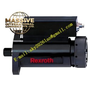
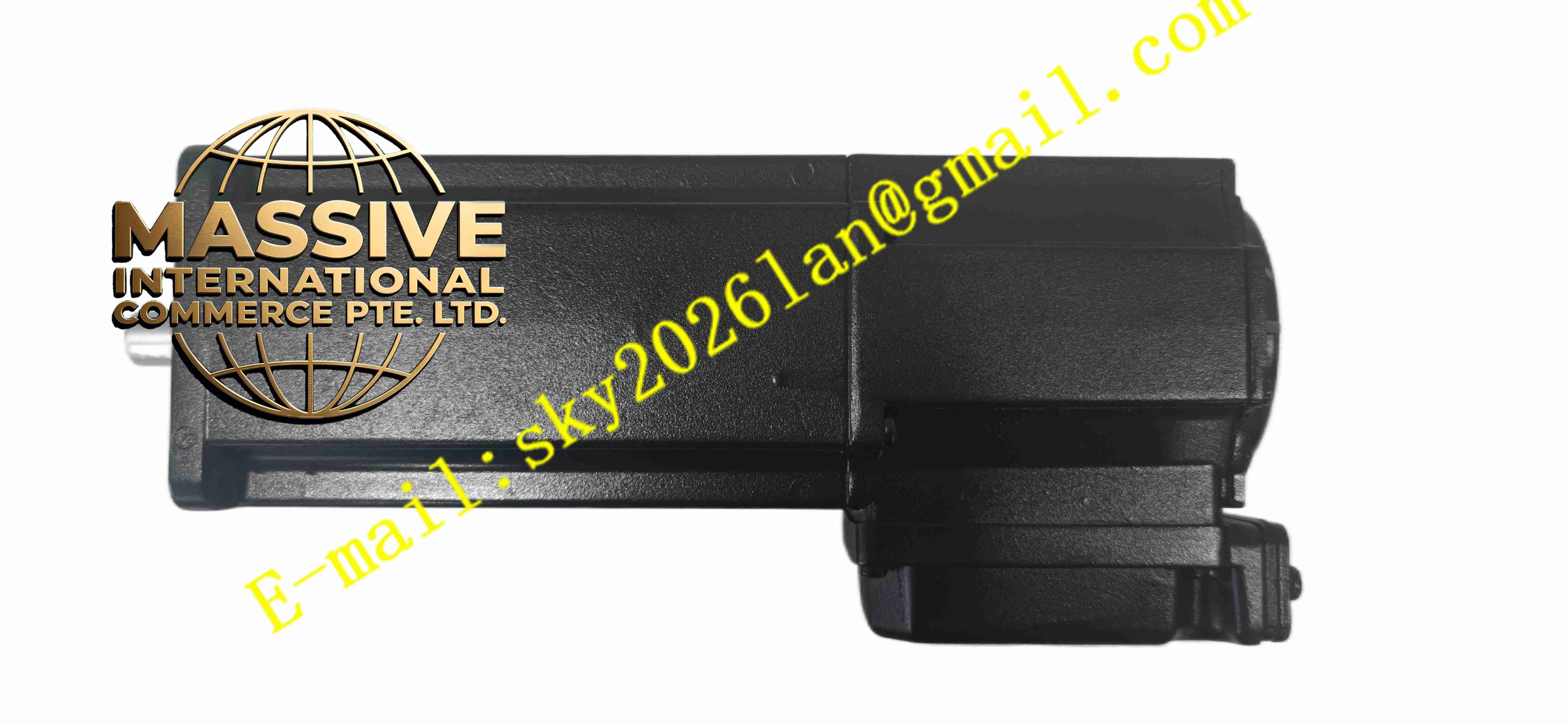
Bosch Rexroth MKD041B-144-KG1-KN
Technical Specifications MKD041 small frame size; permanent magnet synchronous structure; resolver position feedback; 400V class three-phase winding; low inertia rotor; flange mounting; IP65 protection rating; built-in holding brake; standard smooth shaft.
Functional Features Low rotor inertia enables rapid acceleration and deceleration; resolver feedback maintains stable signal under vibration environment; integrated electromagnetic holding brake locks shaft when power cuts off; low cogging torque guarantees smooth low-speed movement; compact housing reduces machine installation space; overload capability supports short peak torque output.
Application Scenarios Small packaging machine servo axis; electronic assembly machine positioning axis; labelling machine drive; small CNC auxiliary feed axis; robot end effector joint.
Performance Parameters Operating ambient temperature -20℃ to +40℃; storage temperature -40℃ to +85℃; relative humidity 5% to 90%, no condensation; vibration and shock resistance meets Rexroth industrial servo standard.
Material Composition Aluminum alloy motor housing; laminated silicon steel stator core; rare-earth permanent magnet rotor; insulated copper winding; stainless steel output shaft; polyurethane shaft lip seal; metal resolver assembly; electromagnetic brake friction disc.
Structural Characteristics Compact cylindrical body with front mounting flange; rear side resolver feedback unit; built-in brake assembly between stator and shaft; side terminal box for power and feedback cable connection; shaft outlet sealing ring to block dust and moisture.
Working Principle Rexroth servo drive supplies three-phase variable frequency AC to stator winding and generates rotating magnetic field. Permanent magnet rotor rotates under magnetic field force. Resolver continuously detects rotor angular position and transmits signal back to servo drive for closed-loop speed and position regulation. When power supply cuts off, electromagnetic brake engages and locks motor shaft mechanically.
Installation Requirements Fix motor flange firmly on machine mounting plate. Select matched shielded power and resolver cable. Align coupling to eliminate shaft misalignment. Complete protective earthing of motor housing. After power-on, perform motor parameter identification in IndraDrive drive and test brake release function.
Usage Notes Do not apply axial impact force to output shaft. Check brake function periodically in safety critical equipment. Keep motor housing surface clean for heat dissipation. Do not disassemble resolver assembly without calibration equipment.