



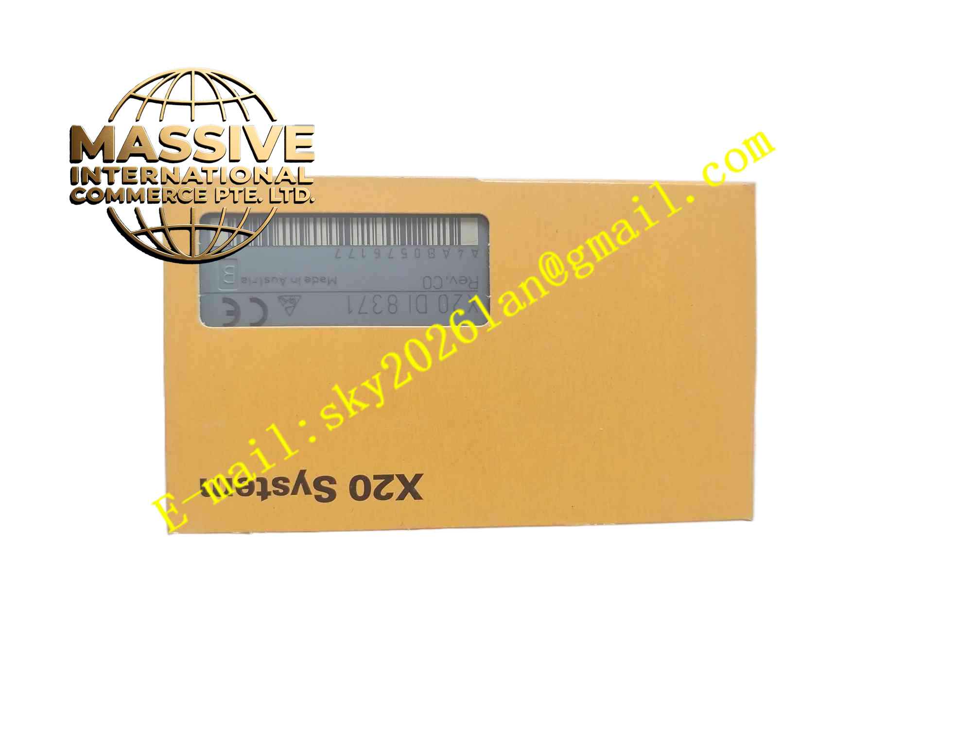
Description
B&R X20DI8371
Technical Specifications: Channel quantity: 8 digital input channels Rated input voltage: 24VDC Input wiring: 1-wire connection Input filter: Configurable digital filter Bus communication: X2X Link Protection class: IP20 Operating temperature: 0℃ to 55℃ Certifications: CE, UL, ATEX Zone 2, DNV
Functional Features: 8 isolated 24VDC digital input channels. Configurable filter to suppress signal bounce and electromagnetic noise. Hardware self-diagnosis for module fault. LED indicators for module running status and fault alarm. Hot swap capability for online replacement. High speed X2X Link backplane data transmission.
Application Scenarios: Automated assembly machines, plastic injection molding machines, material sorting equipment, water treatment control stations, small conveyor systems, printing machinery, marine auxiliary automation equipment.
Performance Parameters: Real-time signal update through X2X backplane bus. High vibration resistance for machine mounted cabinet installation. Stable continuous long-term operation.
Material Composition: FR4 high reliability industrial PCB. Optocoupler isolation components for each input channel. Flame retardant plastic module housing. Gold plated X2X backplane connector. Screw terminal block for field wiring.
Structural Features: Segment modular X20 I/O design. Front panel LED indicators for run and fault status. Side backplane connector to connect adjacent X20 modules. Screw terminal block for field sensor wiring. Stacking installation on X20 bus base.
Working Principle: 24VDC digital signal from field sensors passes through terminal block and optocoupler isolation circuit. Input filter removes signal bounce and high frequency noise. The module converts signal status into digital data and sends to X20 controller over X2X Link bus. Onboard diagnostic circuit monitors module hardware and reports fault status to controller.
Installation Requirements: Install module on X20 bus base module. Use twisted wire for field digital signal wiring. Keep signal cables separated from high voltage power cables. Install within IP20 rated control cabinet. Tighten terminal screws to specified torque.
Usage Notes: Prevent overvoltage applied to input terminals. Set input filter parameter according to field switch characteristics. Power off before disassembly of wiring terminals. Check module LED status after power on.





