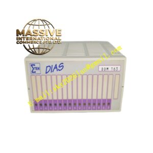

Description
Cameron AAP3798102-00031
Technical Specifications 24V DC nominal power supply with ±10% tolerance; supports Modbus RTU and HART communication protocols; operating temperature range -40°C to +70°C; IP66 enclosure protection; ATEX and IECEx hazardous area certification for Zone 1 and Zone 21; multiple discrete input and output channels for solenoid drive and limit switch feedback; analog input channels for pressure and position feedback.
Functional Features Receives valve opening setpoint commands from the upper control host. Compares commanded position with actual valve position feedback and generates drive signals for hydraulic or electric valve actuators. Monitors solenoid coil current, valve limit switch state and actuator supply pressure. Triggers safety shutdown logic when abnormal pressure or fault conditions occur. Transmits valve position, fault status and diagnostic data to the supervisory control system over fieldbus. Supports local manual operation mode for on-site valve testing.
Application Scenarios Offshore platform production tree valve control, onshore natural gas pipeline safety shutdown systems, oil and gas wellhead choke valve regulation, subsea valve auxiliary control cabinets, compressor station isolation valve monitoring.
Performance Parameters Fast fault response for safety shutdown functions; stable position regulation under fluctuating supply pressure; high noise immunity for offshore and on-site hazardous environments; continuous diagnostic coverage of solenoid and feedback circuits.
Material Composition Main control PCB uses marine-grade FR-4 multilayer flame-retardant substrate; microcontroller and signal conditioning chips are wide-temperature industrial semiconductors; internal isolation components use reinforced optocouplers; enclosure housing is corrosion-resistant coated aluminum alloy; terminal connectors are gold-plated nickel alloy contacts; internal potting compound protects circuits against moisture and vibration.
Structural Characteristics Enclosed rectangular module assembly designed for cabinet or local field mounting. External terminal blocks for power, solenoid outputs, limit switch and instrument feedback wiring. Front panel status LEDs indicate power, communication link, valve state and active faults. Internal potting eliminates free air space inside the housing to meet explosion-proof requirements. External mounting lugs allow direct installation on valve skids.
Working Principle The module receives valve control commands from the host SCADA or DCS system through serial communication. The onboard controller calculates the required actuator drive signal based on position feedback. Output power circuits energize or de-energize solenoid valves to control hydraulic actuator direction. Feedback signals from limit switches and position transducers are sampled continuously. Built-in logic executes predefined safety shutdown sequences when process or equipment faults are detected. Diagnostic circuits monitor coil continuity and wiring short-circuit conditions.
Installation Requirements Mount the module on a vibration-damped valve skid or inside an explosion-proof instrument cabinet. Use certified explosion-proof cable glands for all field wiring entries. Route solenoid power cables separately from low-level analog feedback cables. Configure valve stroke limits, shutdown logic and communication address in Cameron configuration software. Perform full valve stroke test and fault simulation after installation.
Precautions for Use Only use cables and glands certified for the designated hazardous zone. Do not open the enclosure cover when power is applied in explosive atmospheres. Verify solenoid coil voltage rating matches module output specifications. Perform periodic loop testing of safety shutdown functions during scheduled plant shutdowns.