Description
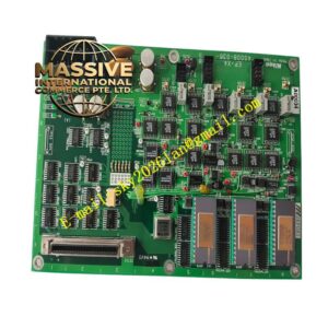
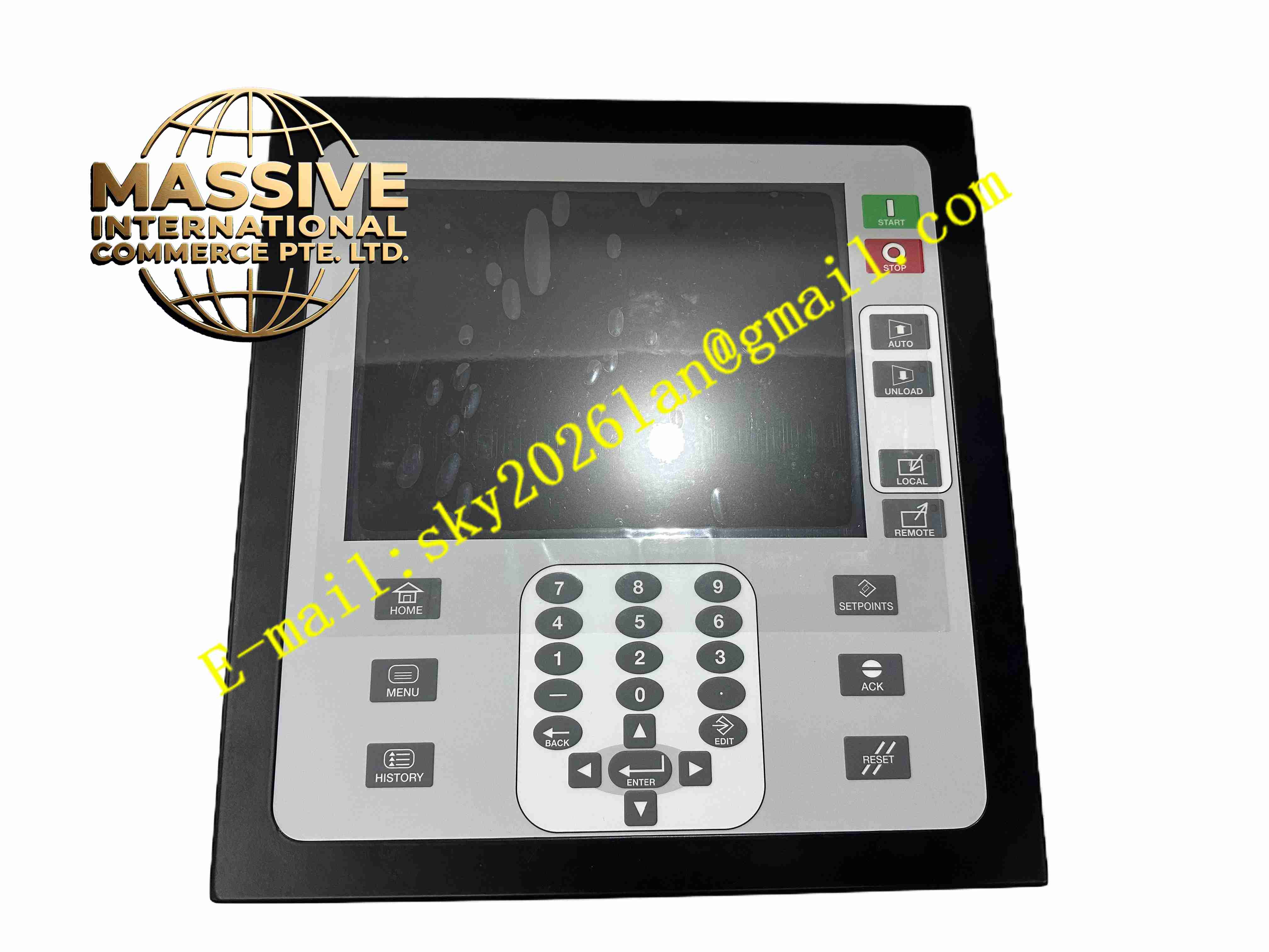
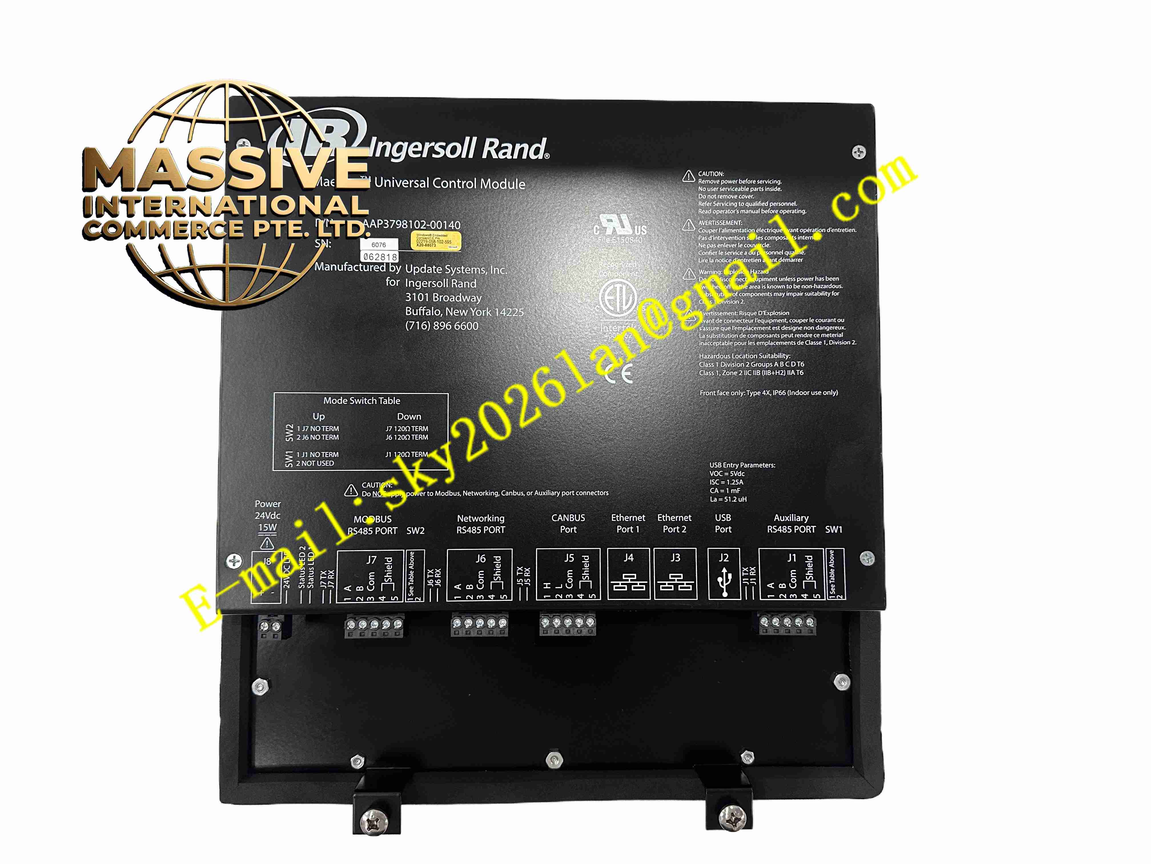
Cameron AAP3798102-00140
Technical Specifications 24V DC power supply; accepts potentiometer and 4-20mA position transducer inputs; discrete limit switch input channels; Modbus RTU and HART communication; operating temperature -40°C to +70°C; IP66 enclosure rating; suitable for NACE corrosive service environments.
Functional Features Samples continuous analog position signals from valve position transducers and converts raw readings into percentage opening values. Compares continuous transducer position against discrete open and closed limit switch status to detect position mismatch faults. Performs transducer calibration to map raw sensor signals to full valve stroke. Detects transducer wire break, short circuit and signal drift faults. Sends calibrated valve position and diagnostic status to the host DCS or SCADA system. Supports local stroke calibration through configuration software.
Application Scenarios Production choke valve position monitoring, pipeline control valve feedback, subsea valve actuator position sensing, wellhead adjustable choke monitoring, offshore platform hydraulic actuator position verification.
Performance Parameters High position measurement resolution for small valve stroke adjustment; consistent calibration stability over long operating cycles; fast fault detection of feedback circuit failure; low measurement drift under temperature cycling.
Material Composition Internal printed circuit board uses FR-4 flame-retardant multilayer substrate; signal conditioning and analog-to-digital conversion chips are wide-temperature industrial semiconductors; isolation circuits use optocoupler devices; module enclosure is corrosion-resistant coated aluminum alloy; terminal contact hardware uses gold-plated corrosion-resistant alloy.
Structural Characteristics Sealed compact rectangular field module with mounting lugs for actuator or cabinet mounting. Front panel LEDs show power, communication link and feedback fault status. External terminal blocks accept position transducer wiring, limit switch wiring and 24V DC power. Internal potting protects electronic components from salt fog, moisture and mechanical shock.
Working Principle Analog position signals from the valve transducer enter the module signal conditioning circuit. The circuit filters and scales the raw signal before analog-to-digital conversion. The onboard microcontroller applies stroke calibration parameters to calculate valve opening percentage. The controller compares calculated position against limit switch state and flags inconsistency faults. Position values and diagnostic codes are transmitted to the supervisory control system over serial communication.
Installation Requirements Mount the module close to the valve actuator to minimize transducer cable length. Use shielded twisted pair cable for position sensor wiring and single-point ground the shield. Perform full stroke calibration by recording fully open and fully closed transducer values. Configure position deadband and fault thresholds in Cameron configuration software.
Precautions for Use Avoid running transducer cables alongside high-current solenoid power cables. Re-calibrate valve stroke after mechanical actuator maintenance. Do not open the sealed enclosure in classified hazardous locations while energized.