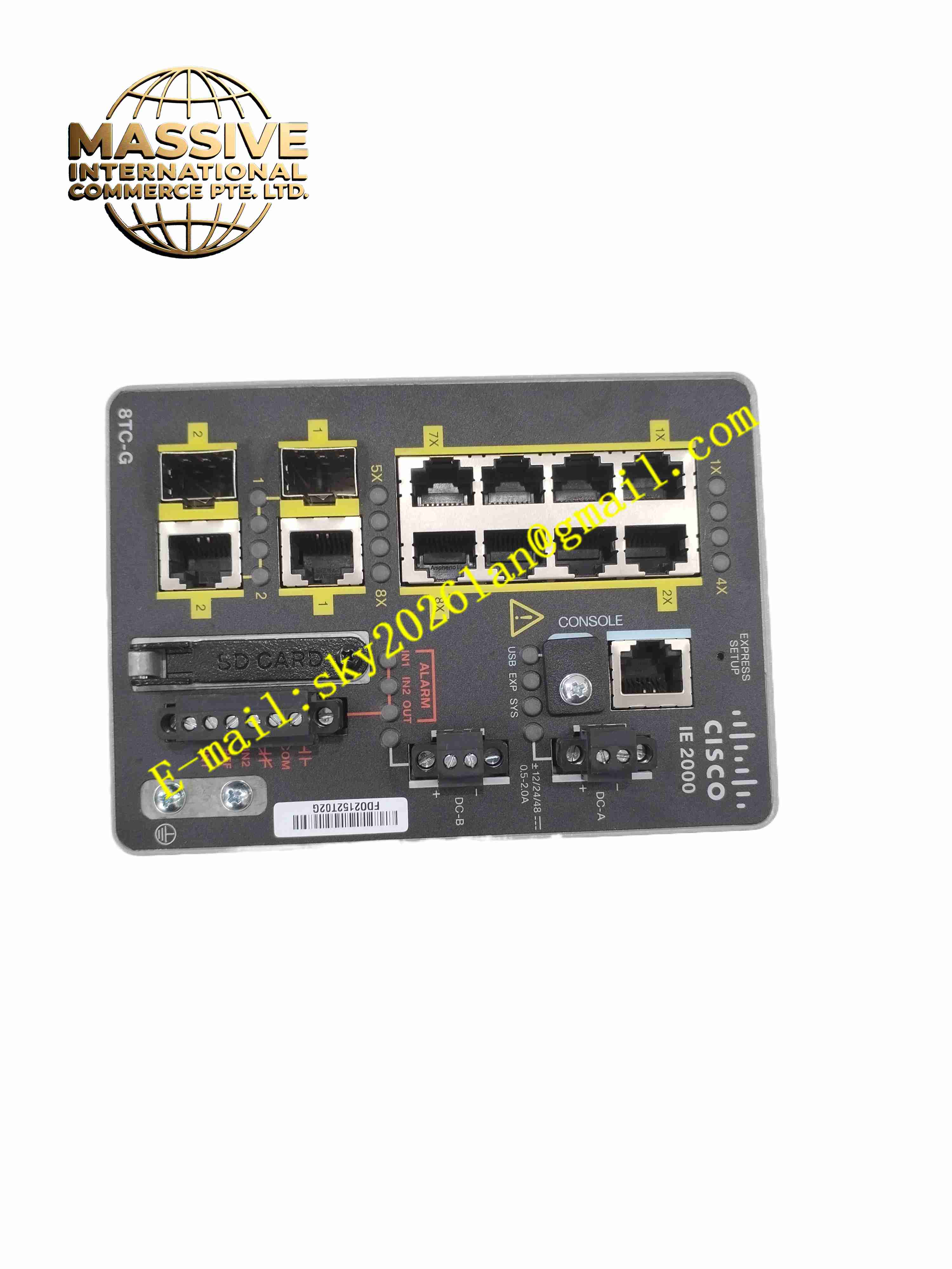
Description
Cisco IE-2000-8TC-G-B
Technical Specifications
- Product Type: Industrial Layer 2 managed Ethernet switch
- Downlink Ports: 8 × 10/100BASE-T RJ45 copper ports
- Uplink Ports: 2 × Gigabit combo ports, 10/100/1000BASE-T or SFP fiber
- Firmware Image: LAN Base
- Power Supply: Redundant DC input, operating range 9.6 V DC to 60 V DC, nominal 12 V / 24 V / 48 V DC
- Alarm Interface: 2 dry contact alarm inputs, 1 relay alarm output rated 48 V DC, 0.5 A
- Memory: 256 MB DRAM, 128 MB flash storage
- Mounting: DIN rail mounting, wall mounting
- Ingress Protection: IP30
- Operating Temperature: -40 °C to +75 °C
- Certifications: CE, UL, ATEX, IECEx, RoHS
- Weight: 1.8 kg
Functional Features
- Layer 2 switching function supports VLAN, trunking, QoS and port security.
- Industrial redundancy protocols including RSTP, MSTP and ERPS for fast network recovery.
- Gigabit combo uplink ports support copper or fiber media for long distance connection.
- Hardware alarm relay output sends notification for power loss or port failure.
- Wide temperature range adapts to extreme hot and cold industrial cabinet environments.
- Redundant dual DC power input prevents single power supply failure interruption.
- SNMP, SSH and web browser interface for remote configuration and status monitoring.
- Port storm control suppresses broadcast storm to protect automation network.
- IEEE 802.1p QoS prioritizes real-time control data over non-critical background traffic.
- Conformal coating option protects PCB against moisture and corrosive gas.
Application Scenarios
- Factory automation PLC and HMI industrial network
- Power substation communication network
- Railway wayside control system data transmission
- Oil and gas field site control network
- Water treatment plant distributed control network
Material Composition
- Enclosure: Die-cast aluminium alloy with powder coating
- Main PCB: FR4 printed circuit board, conformal coating optional
- Network transceiver: Industrial grade Ethernet PHY chips
- Processor: Industrial network management processor
- Terminal blocks: Tin-plated copper alloy screw terminals for DC power and alarm contacts
- Connectors: Gold plated RJ45 and SFP receptacles
Structural Characteristics
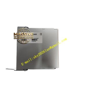
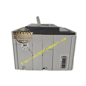
- Compact rectangular metal housing with DIN rail clip on rear side.
- Front panel integrates RJ45 ports, SFP slots, LED status indicators and alarm terminals.
- Internal passive convection cooling design without fan.
- Isolation structure separates power circuit and signal circuit.
- Metal housing provides electromagnetic shielding for industrial noise immunity.
Working Principle After power on, the switch initializes IOS firmware and configures port parameters. It receives Ethernet frames from connected field devices, reads destination MAC address and forwards frames to corresponding port. RSTP protocol calculates network topology and blocks redundant links to avoid loop. When network link fails, redundancy protocol recovers communication within milliseconds. Alarm circuit monitors power status and port link state, triggers relay output when fault condition occurs. SNMP agent uploads device status to upper network management system.
Installation Requirements
- Mount switch on standard 35 mm DIN rail or flat cabinet wall.
- Use shielded twisted pair industrial Ethernet cable for RJ45 connections.
- Separate DC power wiring from high voltage power cables.
- Connect protective earth wire to cabinet ground bar.
- Configure VLAN, redundancy protocol and QoS parameters before commissioning.
- Test alarm relay function by simulating power loss and port disconnection.
- Verify network recovery speed during link failure simulation.
Usage Notes
- Do not exceed DC input voltage range.
- Keep ventilation gaps clear to maintain passive heat dissipation.
- Backup switch configuration file before firmware upgrade.
- Disconnect power before modifying wiring or replacing SFP modules.
- Use anti-static wristband when handling SFP transceivers.
- Replace unit immediately when permanent port or management hardware fault occurs.