Description
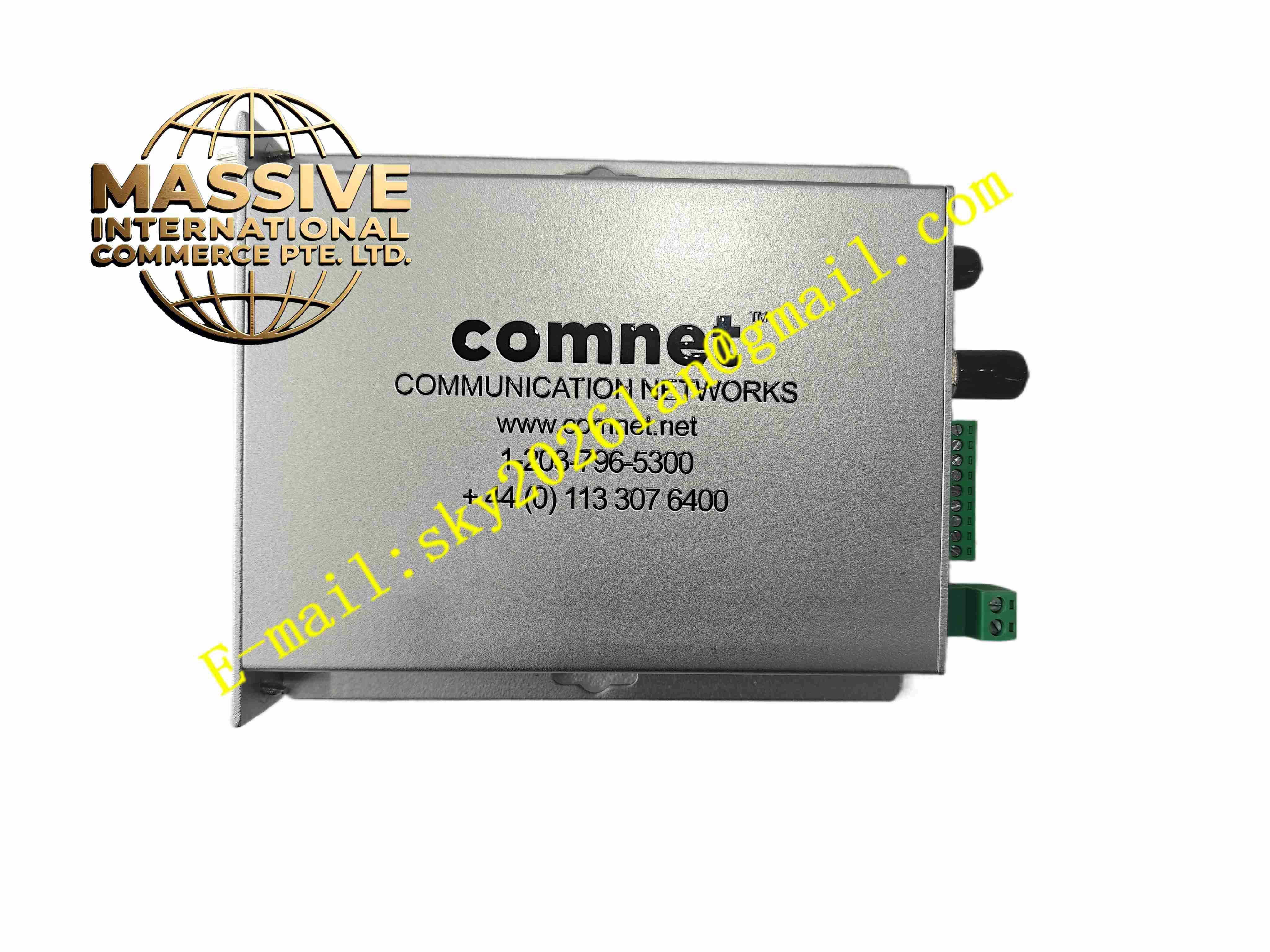
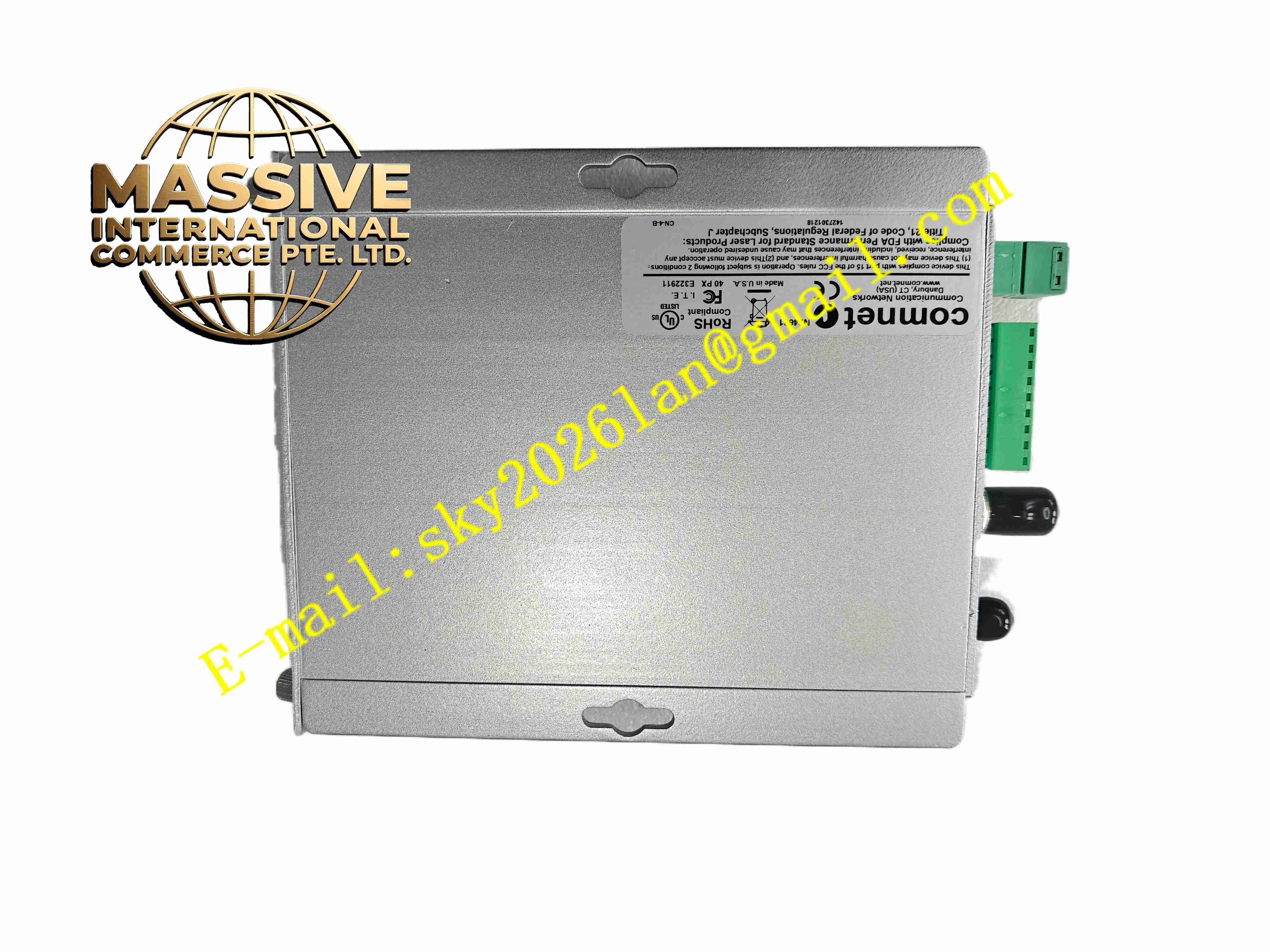
ComNet FVR110M
Technical Specifications:
- Fiber Type: Multimode optical fiber
- Video Format: 10-bit digital encoded EIA RS-250C video
- Video Input via Fiber: 1 V peak-to-peak, 75 ohm
- Video Bandwidth: 5 Hz to 10 MHz
- Differential Gain: Less than 2%
- Differential Phase: Less than 0.7 degree
- Signal to Noise Ratio: 67 dB at maximum optical loss budget
- Data Interfaces: RS232, RS422, 2/4-wire RS485, UTC up-the-coax
- Data Rate: DC to 250 kbps for NRZ format
- Contact Output: SPST relay, 0.5 A contact rating
- Power Supply: 12 to 24 VDC
- Operating Temperature: -40 °C to +74 °C
- Storage Temperature: -40 °C to +85 °C
- Optical Connector: ST fiber port
Function Features:
- Recover 10-bit digital video signal from multimode fiber and output analog composite video
- Bi-directional transparent serial data transmission for camera PTZ control
- Receive dry contact closure signal from transmitter side and output relay contact
- Built-in status LED indicators for optical link, video, data and contact signal
- DIP switch configuration for different serial data modes
- Galvanic isolation eliminates ground loop noise between camera and control room
- No video degradation over fiber transmission path
- Support major CCTV camera control protocols including Pelco Coaxitron and Panasonic Bilinx
Application Scenarios:
- Industrial plant CCTV video monitoring system
- Oil refinery and gas station security camera fiber transmission
- Traffic monitoring camera long-distance signal extension
- Power substation video and PTZ control transmission
- Building security fiber-optic video surveillance systems
Material Composition:
- Housing: Aluminum alloy metal enclosure
- Main PCB: FR4 fiberglass printed circuit board
- Core Components: Optical receiver module, video decoder chip, serial data transceiver
- Terminals: Screw copper terminal blocks for data and power wiring
- Fiber Connector: ST metal fiber receptacle
- Passive Components: Precision resistors, capacitors and surge suppression diodes
Structural Features:
- Compact metal ComFit housing, support wall mount, rack mount or DIN rail mount with adapter
- Front panel with bi-color LED status indicators and DIP switch bank
- ST fiber port on front panel for multimode fiber connection
- Side terminal blocks for power, serial data and relay contact wiring
- Internal metal shielding to block electromagnetic interference
Working Principle: The optical receiver diode converts incoming optical signal from fiber back into electrical digital signal. The onboard decoder chip reconstructs analog composite video signal and outputs to BNC port. Serial data and contact closure information separate from video stream are decoded and routed to terminal block interfaces. The relay activates when contact closure signal is received from transmitter side. The module continuously monitors optical link quality and triggers LED alarm when fiber link breaks.
Installation Requirements:
- Mount unit inside dry control cabinet
- Use ST terminated multimode fiber patch cord to connect FVT110M transmitter
- Use 75 ohm coaxial cable for analog video output
- Use shielded twisted pair cable for serial data wiring
- Connect 12–24 VDC power supply and protective earth
- Set DIP switches to match serial data protocol of field equipment
- Keep fiber connector clean and avoid excessive fiber bending radius
Usage Notes:
- Match FVR110M receiver with FVT110M transmitter as paired set
- Avoid touching fiber end face to prevent contamination
- Do not exceed maximum optical loss budget for multimode fiber link
- Check DIP switch setting before power-on
- Disconnect power before changing DIP switch configuration
- Inspect fiber connectors for dirt during periodic maintenance