Description
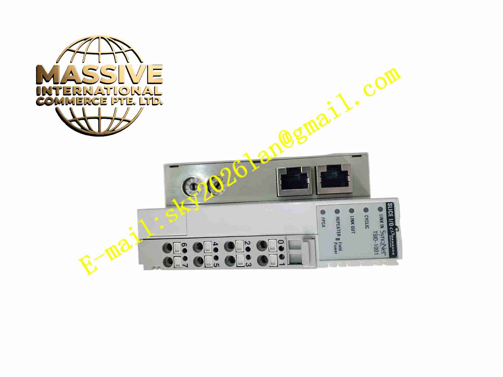
Danaher TSIO-1001
Technical Specifications Combined digital input and digital output channels; Isolated field interface; Operating power supply DC24V; Input signal compatible with NPN and PNP sensors; LED status indicators for each channel; Bus communication interface for motion controller; Operating temperature 0°C to +60°C; DIN rail mounting structure.
Functional Features Galvanic isolation between field I/O circuit and control bus circuit; Per-channel LED status indication; Real-time channel diagnostic for open circuit and overload; Bus data transmission with cyclic refresh; Supports remote I/O deployment near machine; Short-circuit protection for output channels; Configurable input signal filter to suppress contact bounce noise.
Application Scenarios Machine tool safety limit and home switch signal collection; Packaging machine remote sensor acquisition; Robotic peripheral signal control; Material processing equipment local I/O expansion; Conveyor safety interlock signal monitoring; Automated test bench digital signal interface.
Performance Parameters Input signal filtering time is configurable; Channel state update cycle is fixed; Isolation voltage withstand capability meets industrial requirement; Fault detection response is rapid; Signal transmission stability under electromagnetic interference environment.
Material Composition Flame-retardant plastic enclosure; Glass fiber printed circuit board; Optocoupler isolation devices; Transistor output circuits; Bus communication chip; Screw terminal blocks; LED status lights; Surface mount signal conditioning components.
Structural Features DIN rail snap-on compact module; Front panel terminal blocks for field sensor wiring; LED indicators aligned with each I/O channel; Internal opto-isolation barrier separates field and control circuits; Side locking tab for DIN rail mounting.
Working Principle Digital input channels receive on-off signals from proximity sensors, limit switches and emergency stop switches. Optocoupler converts field signal level to internal logic level and transfers signal to bus communication chip. The chip packages I/O state data and transmits data to main motion controller over field bus. For output channels, bus commands arrive at module, optocoupler drives output transistor to switch field load. The module continuously monitors channel status and detects wiring faults.
Installation Requirements Mount module vertically on standard DIN rail; Use shielded cable for bus communication wiring; Single-point grounding for cable shield; DC24V power wire cross-section meets rated current requirement; Keep module away from high-current power contactors and motor drives.
Precautions for Use Cut off DC24V power before wiring operation; Set input filter parameters according to sensor type; Do not exceed maximum load current of output channels; Periodically inspect terminal block for loose wires; Avoid installation in high vibration locations.