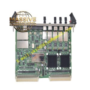
Description
DEIF AGCGS3
Technical Specifications Power supply range 8V DC to 36V DC; measurement of 3-phase voltage, current, frequency, power factor, active power and reactive power; configurable digital inputs and relay outputs; supports CAN bus, Modbus RTU and Ethernet communication; operating temperature range -20°C to +70°C; protection class IP20 for front panel, IP00 for rear wiring area; LCD graphic display with backlight.
Functional Features Performs automatic start and stop sequences for diesel and gas generators. Executes generator synchronization with mains or other parallel gen-sets. Enables active and reactive load sharing among multiple running generators. Provides comprehensive electrical protection including overvoltage, undervoltage, overfrequency, underfrequency, overcurrent, reverse power and loss of excitation. Logs fault events, run hours, maintenance reminders and trend data. Supports remote monitoring and parameter modification via communication interfaces. Offers local manual control mode for on-site commissioning and testing.
Application Scenarios Standby emergency power plants, marine generator systems, remote off-grid power stations, commercial building backup generators, industrial prime power generation installations.
Performance Parameters High-precision voltage and current sampling with low measurement drift; fast protection response time for electrical faults; stable synchronization algorithm under fluctuating grid conditions; continuous data logging with non-volatile memory storage.
Material Composition Front panel uses flame-retardant ABS plastic with anti-glare coating; internal PCB adopts FR-4 flame-retardant multilayer substrate; measurement and processing chips are industrial wide-temperature semiconductors; rear terminal blocks use nickel-plated copper alloy contacts; relay components use silver alloy contact points.
Structural Characteristics Panel-mount rectangular housing for standard control cabinet cutout. Front panel contains LCD display, status LED indicators and tactile membrane push buttons. Rear side includes screw terminal blocks for power, CT/PT signals, digital inputs and relay outputs. Built-in mounting flanges with fixing holes secure the controller to cabinet panels.
Working Principle Voltage and current signals from generator instrument transformers feed into onboard sampling circuits. The microcontroller calculates electrical parameters continuously and compares measured values against configured protection setpoints. When auto mode is active, the controller executes start/stop logic and synchronisation sequences, and adjusts governor and AVR outputs to balance load. Fault conditions trigger relay outputs for generator shutdown and alarm signalling.
Installation Requirements Cut a matching rectangular opening in the control cabinet panel and insert the controller from the front. Secure the unit with the included mounting clamps. Wire voltage transformers, current transformers, battery supply, engine inputs and actuator outputs to rear terminals following the wiring diagram. Configure CT ratio, generator rated parameters and protection thresholds in the controller menu. Complete manual and auto mode testing after wiring and power-on.
Precautions for Use Isolate high-voltage CT and PT circuits before wiring work. Do not exceed the rated voltage and current limits of measurement terminals. Keep the controller away from high-power contactors and variable frequency drives to reduce electromagnetic interference. Back up parameter settings before firmware upgrades.