
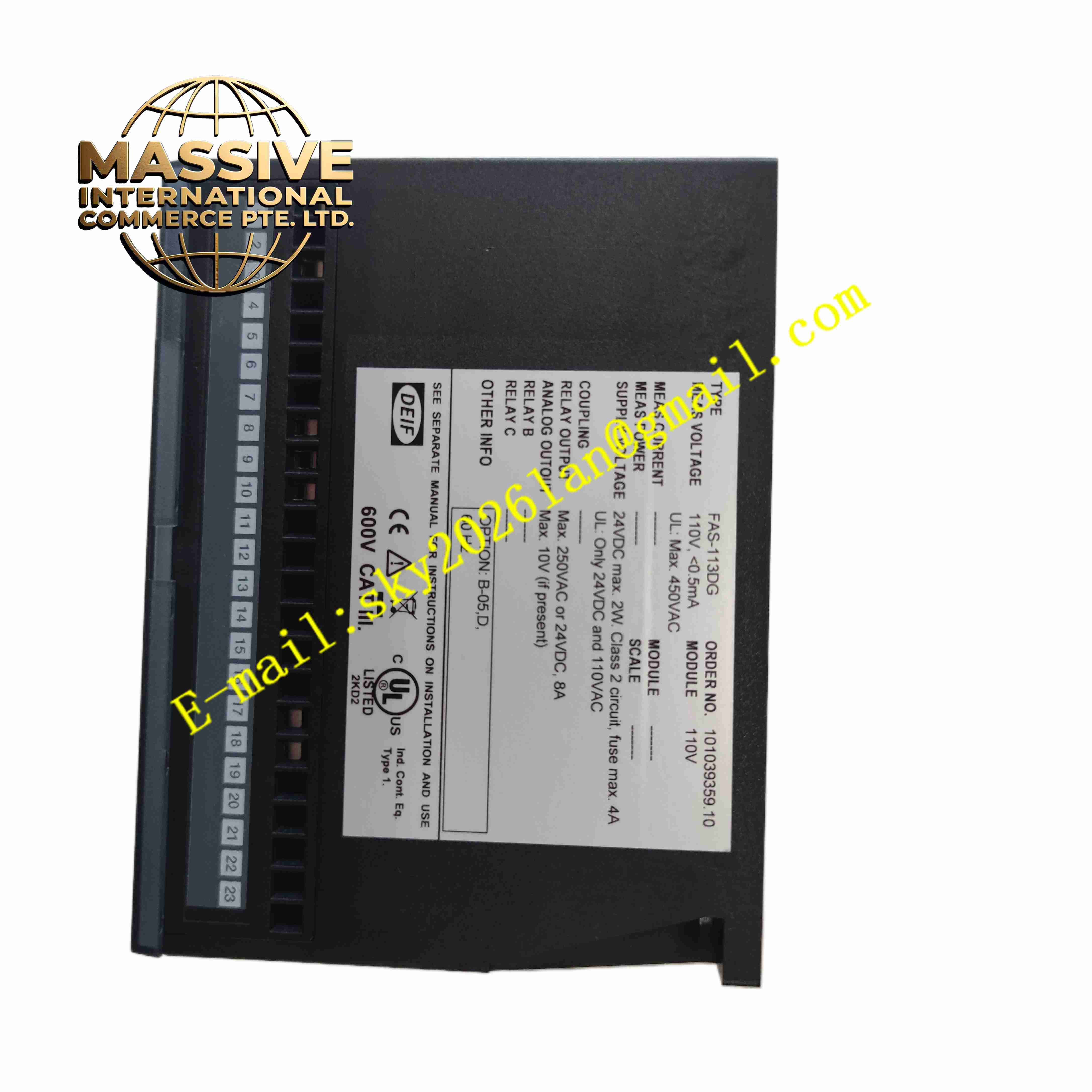
Description
DEIF FAS-113DG
Technical Specifications:
- Measuring Voltage: 40 VAC to 600 VAC, CAT III rated
- Frequency Range: 40 Hz to 70 Hz
- Power Supply: 24 VDC, 18–32 VDC
- Synchronization Accuracy: Adjustable phase and voltage threshold
- Operating Temperature: -20 °C to +70 °C
- Storage Temperature: -40 °C to +85 °C
- Weight: 800 g
- Mounting: DIN rail mounting
- Communication: Modbus RTU for remote monitoring
Function Features:
- Continuous measurement of generator voltage, bus voltage, frequency and phase angle
- Pulse output for speed adjustment to match generator frequency with bus
- Pulse output for voltage adjustment to match generator voltage with bus
- Adjustable breaker closing advance time to compensate for mechanical breaker delay
- Configurable voltage difference, frequency difference and phase angle limits
- Block breaker closing command if synchronization parameters exceed limits
- LED indicators for power, synchronizing, breaker status and fault
- Built-in monitoring of VT wire fault and loss of measurement signal
- Support island mode and utility paralleling mode
Application Scenarios:
- Industrial backup generator parallel control systems
- Marine vessel generator power management systems
- Combined heat and power cogeneration plants
- Hydro power small generator synchronization control
- Power station genset retrofit synchronization panels
Material Composition:
- Housing: Flame retardant black plastic DIN rail enclosure
- Main PCB: FR4 fiberglass printed circuit board with conformal coating
- Sampling Components: Isolated voltage transformers and signal conditioning circuits
- Control Core: Industrial microcontroller
- Terminals: Heavy duty screw copper terminals for VT and control wiring
- Passive Components: Surge suppression diodes, precision resistors and capacitors
Structural Features:
- Rectangular plastic housing designed for DIN rail clip mounting
- Front panel with multiple rotary adjustment potentiometers and LED indicators
- Screw terminal blocks arranged on the lower side for field wiring
- Internal separated low voltage signal and power circuit zones
- Small ventilation slots for passive heat dissipation
Working Principle: Voltage signals from generator VT and busbar VT enter the module terminals. The microcontroller samples and calculates voltage amplitude, frequency and phase difference between generator and bus. It sends raise or lower pulses to engine governor to adjust generator speed and sends pulses to AVR to adjust generator voltage. When all three parameters meet preset synchronization window, the module outputs closing signal to generator breaker. If any parameter exceeds limit, the module blocks breaker closing and triggers alarm indication.
Installation Requirements:
- Install module on DIN rail inside generator control cabinet
- Maintain correct VT polarity for generator and bus voltage wiring
- Separate VT measurement cables from high current power cables
- Use shielded twisted pair cable for Modbus RTU communication
- Connect protective earth terminal to cabinet earth bar
- Avoid mounting near high vibration sources and heat sources
Usage Notes:
- Set generator rated voltage, frequency and breaker closing advance time before commissioning
- Perform synchronization simulation test before live bus test
- Verify VT wiring integrity and polarity before powering on
- Disconnect all VT voltage inputs before maintenance
- Inspect terminal tightness regularly due to genset vibration
- Adjust potentiometer settings to match generator governor response speed