Description
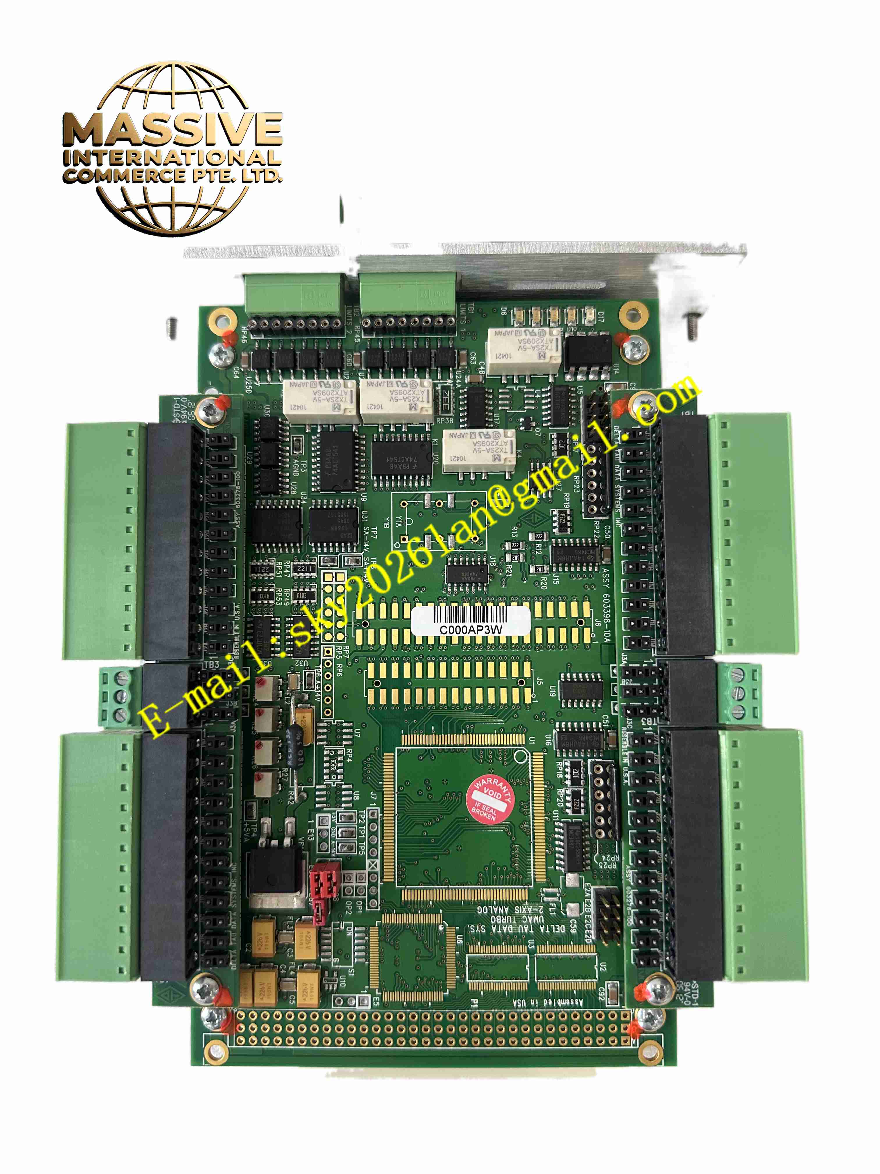
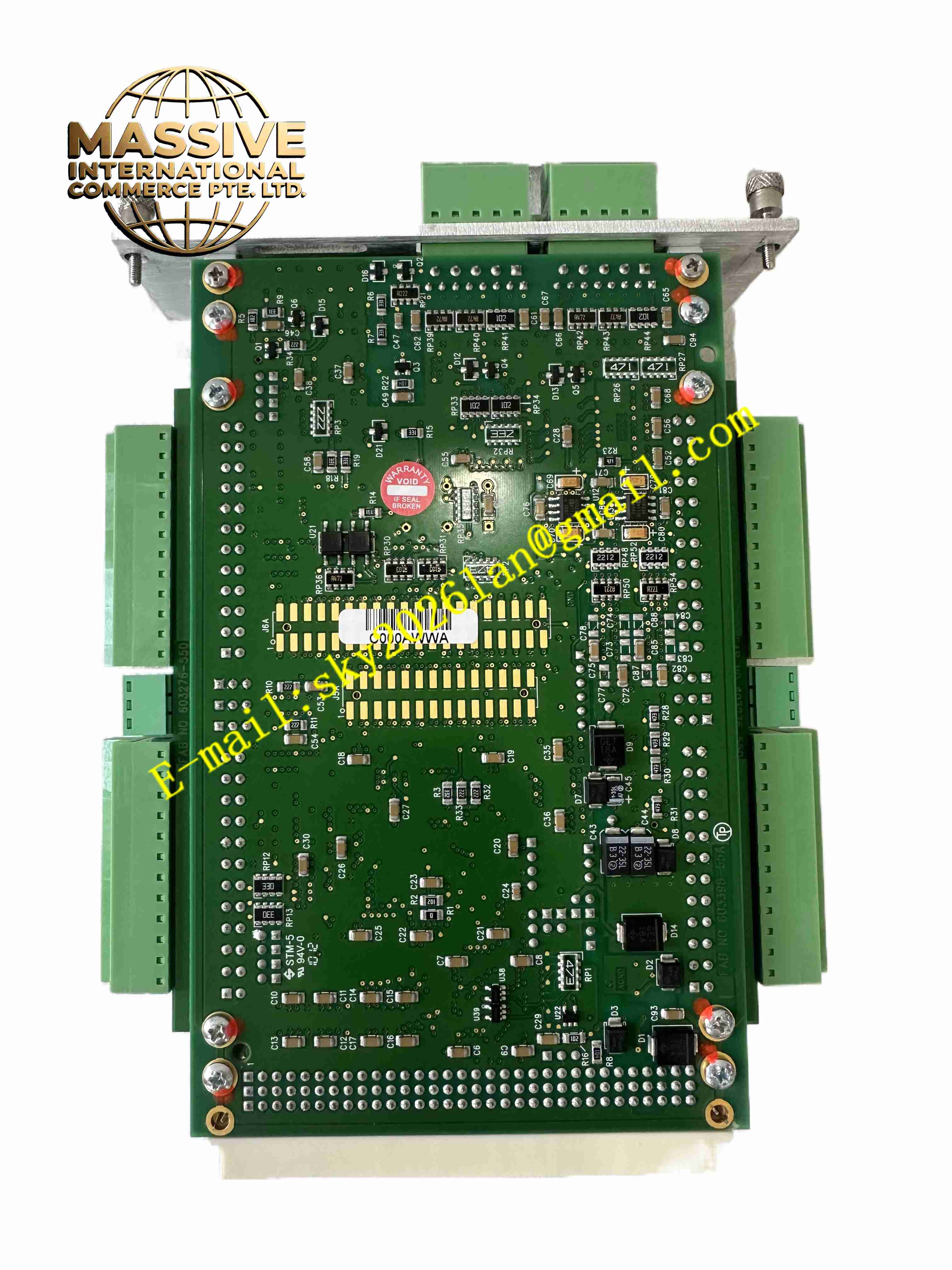
Delta Tau ACC-24E2A
Technical Specifications
- Brand: Delta Tau Data Systems (now part of Omron)
- Model: ACC-24E2A
- Product Type: Analog Servo Interface Expansion Board
- Series: ACC-24E2x Family for UMAC/MACRO Station
- Compatible Controllers: UMAC, Ultralite PMAC, MACRO Station CPU
- Control Channels: 2 channels standard (base board), expandable to 4 channels with OPT1A daughter board
- Command Output Type: Analog ±10V (Velocity or Torque)
- Encoder Inputs: 3-channel differential/single-ended per axis (ABZ)
- Digital I/O per Axis: 8 general-purpose inputs, 2 general-purpose outputs
- Power Supply: ±15V DC (supplied via UMAC backplane)
- Operating Temperature: 0°C to 60°C
- Mounting Format: 3U Rack-mount Eurocard
- Part Number Series: 3A0-603398-10x (Base), 301-603398-10x (OPT1A)
Functional Features
- Provides precise analog ±10V command outputs for velocity or torque control of servo drives
- Supports pulse and direction output commands for stepper systems or MLDT interfaces
- Features 3-channel differential encoder inputs per axis for high-resolution position feedback
- Includes 8 digital inputs and 2 digital outputs per axis for limit switches, home sensors, and general I/O
- Modular design allows expansion from 2 axes to 4 axes using the OPT1A daughter board
- Compatible with any UMAC or MACRO Station CPU via the expansion port
- Supports up to 8 ACC-24E2A boards per UMAC system (up to 32 servo channels total)
- Independent servo loop control with support for feedforward and PID tuning via PMAC software
- High-speed sampling and processing capabilities for real-time control response
- Configurable for single-ended TTL or differential encoder signals
Application Scenarios
- CNC Machine Tools: High-precision milling, turning, and grinding operations requiring analog servo drive control
- Industrial Robotics: Multi-axis robotic arms requiring precise trajectory control and torque management
- Semiconductor Manufacturing: Wafer handling equipment, lithography stages, and precision positioning systems
- High-Speed Packaging Machinery: Synchronized multi-axis motion for filling, capping, and labeling operations
- Automated Assembly Systems: Pick-and-place robots and assembly line coordination
- Textile and Printing Machinery: High-speed web handling and registration control
- Test and Measurement Equipment: Precision motion stages for material testing and inspection
Performance Parameters
- Analog Output Resolution: 16-bit DAC (typical for PMAC2-type servo IC)
- Command Output Range: ±10V DC
- Encoder Input Frequency: Up to several MHz (depending on configuration)
- Digital I/O Response Time: Sub-millisecond response for limit and home signals
- Servo Loop Update Rate: Determined by host PMAC CPU (typically 250 µs to 1 ms)
- Maximum Axes per System: 32 analog servo channels (8 boards × 4 channels)
- Signal Isolation: Buffered I/O for noise immunity in industrial environments
- Communication Interface: UBUS high-speed parallel bus to UMAC CPU
Material Composition
- PCB Substrate: Industrial-grade FR-4 fiberglass epoxy with multi-layer construction
- Connector Terminals: Gold-plated or tin-plated copper alloy pins for reliable signal transmission
- Servo IC: Highly integrated PMAC2-type servo integrated circuit (ASIC)
- Passive Components: Precision metal-film resistors, ceramic and electrolytic capacitors
- Connector Housing: DB15 or terminal block connectors made from thermoplastic materials
- Front Panel: Aluminum or steel plate with silk-screened labeling
- Conformal Coating: Protective coating on PCB for moisture and contaminant resistance
Structural Features
- Standard 3U Eurocard form factor for insertion into UMAC rack chassis
- Base board provides 2 servo channels; OPT1A daughter board adds 2 more channels
- Front-panel accessible connectors for servo commands, encoder feedback, and digital I/O
- LED indicators for power status and channel activity
- Keyed connector interfaces preventing incorrect cable insertion
- Robust mechanical construction for vibration resistance in industrial environments
- Heat dissipation design relying on chassis airflow for cooling
- Clear silk-screen labeling for pin identification and channel assignment
- Removable terminal block options available for simplified wiring
Working Principle
The ACC-24E2A operates as a signal conversion interface within the Delta Tau motion control architecture. The UMAC CPU executes motion control algorithms (position, velocity, torque loops) and generates digital command values. These digital values are transmitted via the UBUS to the ACC-24E2A’s PMAC2-type servo IC. The servo IC converts the digital commands into analog ±10V voltage signals through internal digital-to-analog converters (DACs). These analog signals are then output to the connected servo drives, which amplify the signals to drive the servo motors.
Simultaneously, the ACC-24E2A receives position feedback from encoders mounted on the motor or machine axis. The encoder signals (A, B, Z phases) are received through differential line receivers, counted by the servo IC’s encoder counters, and transmitted back to the UMAC CPU for closed-loop position control. The digital I/O channels provide real-time status information such as limit switch activation, home position detection, and drive fault signals to the controller, enabling safe and coordinated machine operation.
Installation Requirements
- Install the into an available slot in the UMAC 3U rack chassis
- Ensure the UMAC system is powered down before inserting or removing the board
- Align the board’s edge connector with the backplane slot and firmly seat the board
- Secure the board using the front-panel mounting screws or retaining clips
- Connect servo drive command cables to the appropriate output terminals (±10V)
- Wire encoder feedback cables to the encoder input terminals, observing proper pin assignments
- Connect digital I/O signals (limits, home, alarms) to the designated input/output terminals
- Ensure proper grounding of encoder cable shields to minimize electrical noise
- Configure axis parameters and I/O assignments in the PMAC configuration software
- Verify power supply voltages (±15V) from the backplane before powering up the system
- Perform a thorough check of all wiring connections before energizing servo drives