



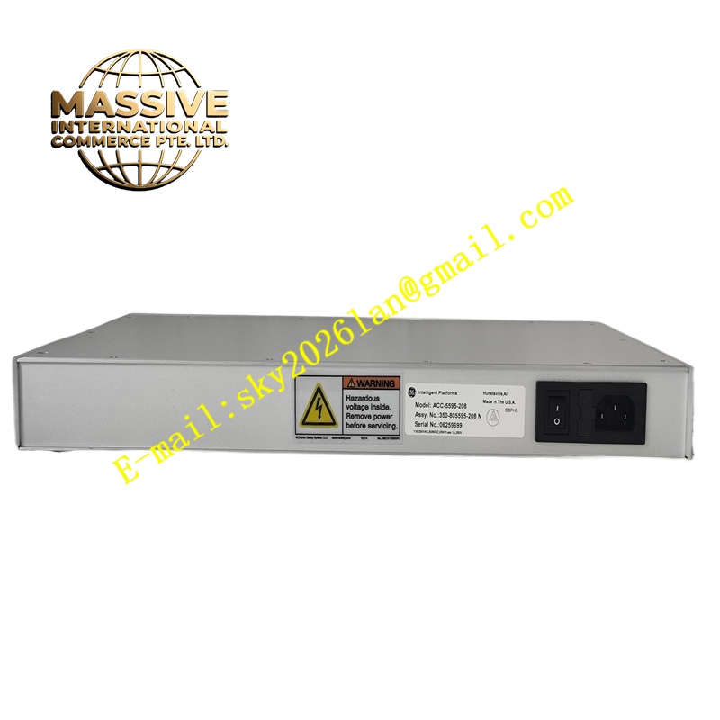
Description
Delta Tau ACC-5595-208
Technical Specifications 8 independent pulse-and-direction output channels; maximum pulse output frequency 10MHz; TTL differential pulse signal level; each channel includes differential enable and fault input signals; powered by PMAC backplane 5V DC; operating temperature -20°C to +70°C; relative humidity 5% to 95% non-condensing.
Functional Features Converts trajectory position commands calculated by the PMAC controller into pulse and direction signals for downstream drives. Generates high-speed pulse streams synchronized with the servo interpolation cycle. Receives drive fault signals and enable feedback signals from stepper and pulse servo amplifiers. Reports drive fault status to the PMAC controller and triggers safety motion halt actions. Supports software configuration of pulse polarity, direction logic and pulse count mode.
Application Scenarios Stepper motor-based automation positioning platforms, small CNC routing machines, dispensing automation equipment, laboratory precision positioning stages, low-cost automated material handling machines.
Performance Parameters High pulse output frequency with low jitter; precise synchronization between pulse output and motion profile; fast response to external drive fault signals; stable pulse waveform transmission over short to medium cable lengths.
Material Composition Main printed circuit board uses FR-4 flame-retardant multilayer substrate; high-speed pulse generation logic chips are industrial semiconductors; differential line drivers and receivers use high-speed transceivers; external connectors adopt gold-plated copper alloy contacts; passive components use high-stability resistors and capacitors.
Structural Characteristics Compact plug-in expansion board matching PMAC carrier slots. High-density edge connectors for pulse, direction and fault signal wiring. Onboard LED indicators display power and channel signal activity. Rear expansion bus connector connects to the PMAC main controller, and mounting holes secure the board inside the chassis.
Working Principle The PMAC main controller calculates target position and speed for each axis and sends digital command values to the ACC-5595-208 board over the expansion bus. Onboard logic chips generate pulse trains and direction level signals according to the command values. Differential drivers send these pulse signals to stepper or pulse servo drives. Fault feedback signals from drives are received by differential receivers and transmitted back to the PMAC controller.
Installation Requirements Power off the PMAC chassis before installing the board. Mount the board in the designated expansion slot of the PMAC carrier. Use shielded twisted-pair cables for pulse and direction signal wiring. Configure pulse output mode, polarity and fault logic in PMAC programming software. Test motor rotation direction and pulse scaling after wiring.
Precautions for Use Keep pulse signal cables short and separated from high-power motor cables. Verify that the connected drive supports differential TTL pulse signals. Adjust electronic gear ratio parameters to match mechanical lead of the axis. Stop motion immediately when drive fault signals are detected.







