Description
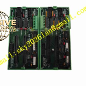
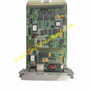
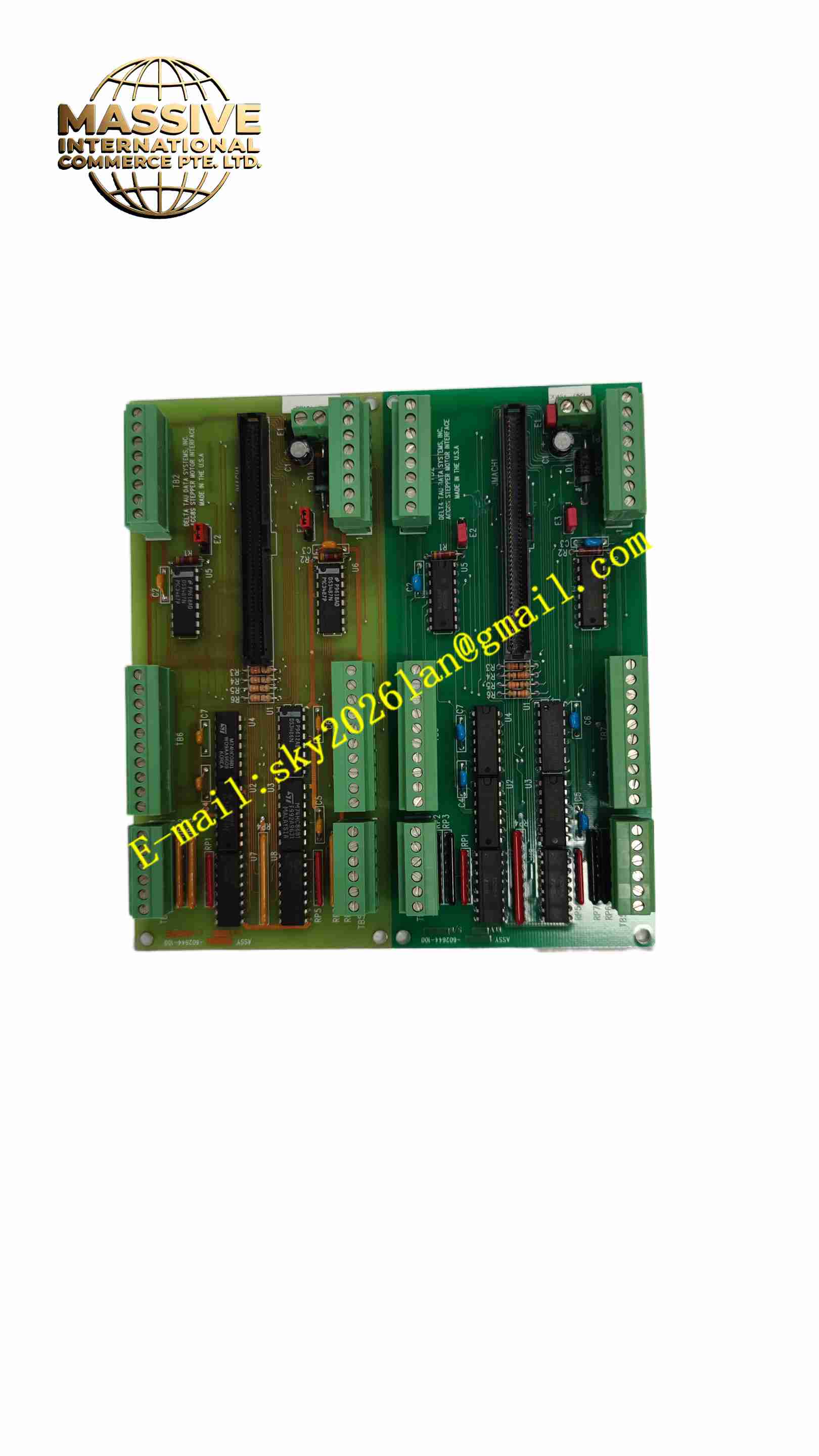
DELTA TAU PMAC-2ACC8S
Technical Specifications Model: PMAC-2ACC8S Controllable Axes: 8 axes Analog Output per Axis: ±10V 12-bit DAC analog servo command output Encoder Input: Differential A/B/C orthogonal encoder input for each axis Digital Input Channels: Axis limit, home, emergency stop digital signal input Communication Bus: Dedicated bus connected to PMAC2 CPU Power Supply: 5VDC, ±12VDC Operating Temperature: -20℃ ~ +70℃ Storage Temperature: -40℃ ~ +85℃ Relative Humidity: 5% ~ 95% non-condensing Board Form: 3U Eurocard rack board Mounting: Industrial standard rack backplane installation
Functional Features 8 independent analog output channels, each channel outputs ±10V analog speed or torque command to analog servo drive. 8 independent differential orthogonal encoder input channels to receive position feedback signal from shaft encoder. Each axis is equipped with digital input interface for limit switch, home switch and emergency stop signal collection. 12-bit DAC conversion ensures high precision analog command output. Signal isolation between field I/O circuit and internal control circuit to reduce external interference. On-board LED indicators display the working status of each axis signal. Support position capture and position comparison output function of each axis. Hardware over-range protection for analog output channels.
Application Scenarios Analog servo drive multi-axis CNC machine tools, packaging machinery multi-axis motion control, web tension control equipment, laser processing equipment, material testing machines, printing machinery, hydraulic proportional valve multi-axis synchronization control system.
Performance Parameters 12-bit DAC analog output with high linearity and low temperature drift. Differential encoder input has strong anti-interference ability for long distance transmission. The response speed of limit and home signal collection meets high-speed motion control requirements. Each analog channel has short-circuit protection function. The board has excellent EMC performance and can resist electromagnetic interference from motors and inverters. The signal sampling maintains high stability during long-term continuous operation.
Material Composition Board Substrate: FR4 multi-layer high-density industrial printed circuit board with conformal coating. Core Electronic Components: 12-bit DAC chip, encoder differential receiving chip, digital signal optocoupler isolation chip, bus interface chip, voltage regulator chip, LED indicator. Connector: Gold-plated Eurocard backplane connector, field signal terminal connector. Panel: Aluminum alloy front panel with status indicator lights. Fasteners: Metal fixing screws and panel locking components.
Structural Features Standard 3U Eurocard plug-in board structure, inserted into the industrial rack and connected with PMAC2 CPU through backplane bus. Aluminum alloy front panel is equipped with LED status indicators for each axis. The backplane gold-plated connector realizes data and power connection with the rack backplane. The edge of the board is equipped with field signal terminals, which are used to connect encoder, servo drive analog command and limit switch cables. The circuit board carries out partition layout for analog output circuit, encoder receiving circuit and digital input circuit to reduce signal crosstalk. Passive heat dissipation through natural air convection inside the rack.
Working Principle After the rack is powered on, PMAC2 CPU sends digital axis command data to PMAC-2ACC8S through the backplane dedicated bus. The DAC chip on the board converts the digital command into ±10V analog voltage signal, which is transmitted to the analog servo drive to control the motor speed or torque. The orthogonal encoder signal fed back by each motor shaft enters the differential receiving circuit of the board, converts it into digital pulse signal and transmits it back to PMAC2 CPU for position closed-loop calculation. The limit, home and emergency stop switch signals of each axis enter the board through optocoupler isolation, and are transmitted to PMAC2 CPU for motion logic judgment. The on-board LED indicators display the signal state of each axis channel in real time. When the analog output channel is short-circuited, the hardware protection circuit triggers to limit the output current and protect the DAC chip.
Installation Requirements Power off the rack before installation, insert PMAC-2ACC8S into the empty slot of the rack, lock the front panel screws. Connect the backplane bus between PMAC-2ACC8S and PMAC2 CPU. Use shielded twisted pair cable for encoder and analog servo command wiring, single-point grounding of shielding layer. Separate the signal cable from the motor power cable and high-power cable. After wiring, power on the rack, use PMAC upper computer software to configure each axis parameter, encoder type and analog output polarity. Carry out single-axis jog test and multi-axis synchronous motion test, verify the analog output and position feedback.
Usage Precautions Wear anti-static wristband when installing and handling the board to prevent static damage to electronic components. Forbid hot swapping the board when the rack is powered on. Do not connect high voltage signal to analog output and encoder input channel, high voltage will burn the board circuit. Regularly check the tightness of field signal terminals in high vibration environment. Keep the rack ventilation unobstructed to avoid overheating of the board. Clean the dust on the board regularly in dusty workshop environment. The replacement board must be PMAC-2ACC8S same model, ACC8T and ACC8S models cannot be directly interchanged without parameter modification.