Description
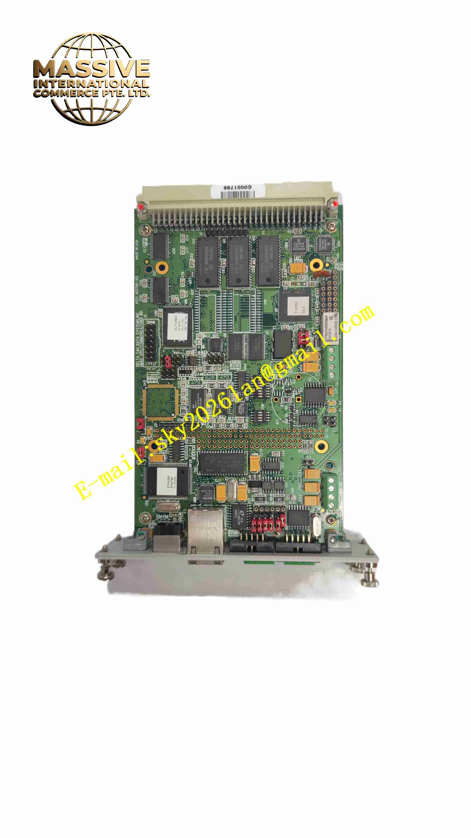
DELTA TAU PMAC2 CPU
Technical Specifications Model: PMAC2 CPU Core Processor: Motorola DSP56 series digital signal processor CPU Main Frequency: 80MHz / 100MHz optional Program Memory: 128k ×24 SRAM, expandable to 512k ×24 Data Memory: 128k ×24 SRAM, expandable Firmware Storage: 1M ~ 2M ×8 Flash memory Position Calculation Precision: 36-bit position counting range Communication Interfaces: RS232 serial port, Ethernet, MACRO fiber bus Encoder Interface: Support differential orthogonal encoder input Operating Temperature: -20℃ ~ +70℃ Storage Temperature: -40℃ ~ +85℃ Relative Humidity: 5% ~ 95% non-condensing Board Form: 3U Eurocard board, rack installation Power Supply: 5VDC, ±12VDC
Functional Features High-speed DSP chip completes real-time trajectory planning and servo closed-loop calculation. Support up to 32-axis synchronous motion control, realize electronic cam, electronic gear, multi-axis interpolation function. Built-in PID, notch filter, feedforward servo algorithm, which can be independently configured for each axis. Support S-curve acceleration and deceleration, cubic spline interpolation and continuous path motion. Multiple communication interfaces realize data exchange with upper computer, servo drives and remote I/O modules. High-precision position capture and position comparison output function for synchronous trigger of external events. Battery backup memory preserves user parameters and motion programs after power failure. On-board self-diagnosis function detects CPU operating status, memory error and communication fault. Support online firmware upgrade through upper computer software.
Application Scenarios CNC machining equipment, laser cutting and laser processing machinery, multi-axis packaging machinery, semiconductor processing equipment, robot motion control, special material test benches, printing and web handling equipment.
Performance Parameters The servo loop calculation can complete high-speed real-time calculation in microsecond level. 36-bit wide position register realizes ultra-long stroke high-precision position counting without overflow. Multi-axis interpolation operation maintains high synchronization accuracy of each axis. The position capture function can record the encoder position at the moment of external trigger signal with high precision. The board has strong EMC anti-interference performance and can work stably in the environment with inverter and motor interference. Battery backup memory can retain user programs and parameters for long time after power off.
Material Composition Board Substrate: FR4 multi-layer high-density industrial printed circuit board with conformal coating. Core Electronic Components: DSP digital signal processor, flash memory chip, SRAM memory chip, communication transceiver chip, encoder signal receiving chip, battery backup circuit, crystal oscillator, voltage regulator chip. Connector: Gold-plated Eurocard backplane connector, serial port and Ethernet metal connector. Fasteners: Metal fixing screws and panel locking components. Panel: Aluminum alloy front panel with status indicator LED.
Structural Features Standard 3U Eurocard plug-in board structure, which can be inserted into the industrial rack backplane. Aluminum alloy front panel is equipped with multiple LED status indicators to display power, running, fault and communication status. Backplane gold-plated connector realizes data and power connection with rack backplane. On-board battery holder for backup lithium battery installation. Circuit board layout separates high-speed digital circuit, analog signal circuit and power supply circuit to reduce signal crosstalk. No fan passive heat dissipation, relying on air convection inside the rack.
Working Principle After the board is powered on, the DSP processor loads the firmware program from flash memory, and reads the user motion program and axis parameters from the battery backup memory. The upper computer downloads motion commands through Ethernet or serial port to PMAC2 CPU. The DSP completes trajectory planning, interpolation calculation, PID servo closed-loop operation, and outputs motion commands to the servo drive through MACRO bus or analog output. The encoder position feedback signal is collected by the on-board encoder interface and sent back to DSP to form a position closed loop. The position capture circuit records the encoder position value when receiving external trigger signal. The on-board self-diagnosis circuit continuously monitors the memory, power supply and communication status, and lights the fault indicator when abnormality occurs. The battery backup circuit supplies power to the memory when the rack main power is cut off to retain user programs and parameters.
Installation Requirements Power off the industrial rack before installation, insert PMAC2 CPU board into the empty slot of the rack, and lock the front panel fixing screws. Connect the backplane cable, Ethernet cable, serial port cable and MACRO fiber according to the system wiring diagram. Install the backup lithium battery into the battery holder on the board. Set the board address and hardware jumpers according to the system configuration requirements. Power on the rack, use the upper computer software to connect to PMAC2 CPU, download the axis parameters and motion programs. Carry out single-axis test and multi-axis synchronous motion test to verify the control performance.
Usage Precautions Static protection must be done when touching and installing the board, wear anti-static wristband to prevent static damage to chips. Do not hot swap the board when the rack is powered on. Regularly check the voltage of the backup lithium battery, replace the battery before the voltage drops below the threshold to prevent parameter loss. Keep the ventilation of the rack unblocked to avoid excessive temperature rise of the board. Avoid strong vibration and impact on the rack where the board is installed. Do not modify the hardware jumper at will after the system is debugged. Firmware upgrade operation cannot be interrupted by power failure, otherwise the firmware will be damaged. The replacement board must be PMAC2 CPU of the same hardware version.