Description
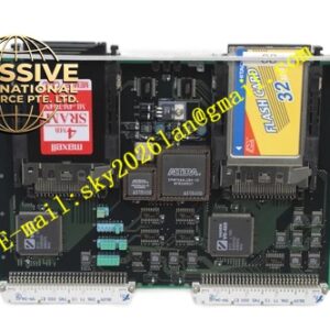
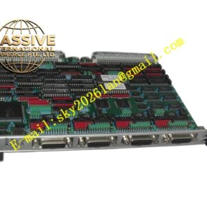
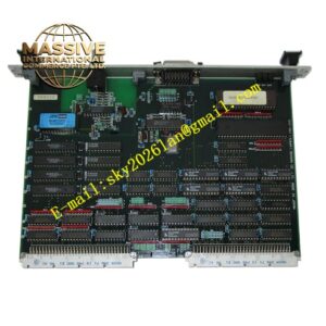
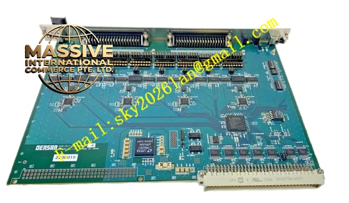
Densan DVE‑511‑PBF (9559A)
Technical Specifications: Bus compliance: VME bus standard ANSI/IEEE 1014 Form factor: 6U single‑slot VME plug‑in module Number of serial channels: 8 independent channels Interface mode per channel: jumper configurable RS‑232C, RS‑422, RS‑485 Baud rate range: 50 bps up to 921600 bps Power consumption: 7.2 W, powered by VME backplane 5 VDC, ±12 VDC Operating temperature: 0 ℃ to 55 ℃ Storage temperature: -40 ℃ to 85 ℃ Relative humidity: 5% to 95% non‑condensing Protection grade: IP20 Backplane connector: DIN 41612 J1 connector
Functional Features: Eight fully independent asynchronous serial channels. Hardware jumper configuration for each channel interface standard. On‑board hardware FIFO buffer for transmit and receive data to reduce VME bus interrupt frequency. Front‑panel LED indicators for transmit activity, receive activity and power status. Built‑in EMC surge suppression circuit for each serial port. Complete power‑on hardware self‑diagnosis routine. VME bus interrupt trigger when receiving data or buffer threshold reached. Lead‑free PBF soldering technology for extended service life. Support full‑duplex and half‑duplex communication modes. Channel‑wise readable status register via VME bus access.
Application Scenarios: Semiconductor wafer processing equipment control racks, automated test equipment serial peripheral connection, industrial robot controller peripheral communication, factory automation VME‑based control system, laboratory automatic pilot test apparatus, packaging and assembly production line monitoring units, old‑generation industrial equipment renovation projects requiring multi‑port serial expansion.
Performance Parameters: Maximum per‑channel baud rate: 921600 bps FIFO depth per channel: 256 bytes for transmit, 256 bytes for receive Vibration resistance: 10 Hz‑150 Hz, 0.5 g constant amplitude Shock resistance: 10 g peak acceleration, 11 ms duration pulse MTBF value: 192000 hours under cabinet forced‑air cooling environment
Material Composition: Front panel adopts oxidation‑resistant extruded aluminum alloy with matte surface treatment. Main printed circuit board uses high‑Tg FR‑4 glass‑fiber epoxy substrate complying with UL94‑V0 flame retardant standard. Backplane connector contact pins apply hard gold‑plated copper‑alloy material. Serial transceivers and logic chips are industrial‑grade integrated circuits with wide temperature range. All soldering processes follow lead‑free PBF specification. Fastening hardware consists of nickel‑plated carbon steel screws and spring latches.
Structural Features: Standard 6U double‑height single‑slot VME plug‑in mechanical structure. Metal front panel fitted with locking ejector handles and array of LED status indicators. Rear side equipped with multi‑row DIN 41612 gold‑plated connector for mating with VME rack backplane. Internal PCB implements strict layout zoning for VME bus logic circuit, serial transceiver circuit and power supply filtering circuit. Independent ground isolation area exists for RS‑422/485 differential signal paths. Decoupling capacitors are densely distributed across every functional circuit block. Small‑size jumper blocks on PCB surface for channel interface mode switching. Panel ventilation cutouts enable passive convection heat dissipation.
Working Principle: After rack power‑on, DVE‑511‑PBF completes full hardware initialization and power‑on self‑test. VME main controller writes configuration parameters to on‑board registers through VME backplane bus to set each channel baud rate, data bit length, parity mode and interface type. When external serial device sends data, transceiver chip receives serial bit stream, stores received bytes into corresponding channel FIFO buffer. Once data volume reaches preset threshold, board generates interrupt signal toward VME bus. VME host reads received data from FIFO register. For data transmission, main controller writes outbound data into transmit FIFO, hardware converts parallel data into serial bit stream and transmits toward field serial equipment. Front‑panel LEDs reflect real‑time transmit and receive activity status of each channel. Fault information can be retrieved by reading dedicated status registers over VME bus.
Installation Requirements: Insert module fully into designated empty slot of standard 6U VME rack chassis. Push ejector handles into locked position and tighten front‑panel mounting screws to guarantee stable mechanical contact with backplane connector. Maintain unobstructed airflow path inside cabinet for heat dissipation. Use shielded twisted‑pair cables for all external serial signal wiring. Separate serial communication cables away from high‑current power and drive cables. Disconnect total rack power supply before inserting or extracting this circuit board. Operators must complete static electricity discharge procedure by touching grounded metal surface before handling bare printed circuit board. Do not modify onboard jumper settings while system remains powered on.
Precautions for Use: Do not apply voltage exceeding transceiver chip rated specification onto serial port external terminals. Wear anti‑static wristband during all maintenance, inspection and replacement operations. Keep front‑panel ventilation openings clean without dust and fiber accumulation. Do not deploy this hardware inside environment containing corrosive vapor, conductive dust or oil mist. Inspect front‑panel screw tightness and connector contact condition during regular equipment maintenance cycles. Back up all channel configuration parameters before board replacement. When running RS‑485 half‑duplex mode, strictly follow bus termination resistor configuration rules for field wiring.