Description
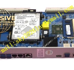
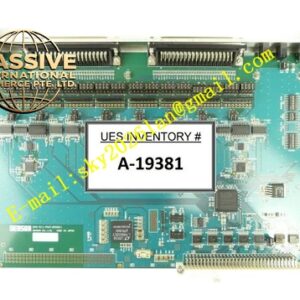
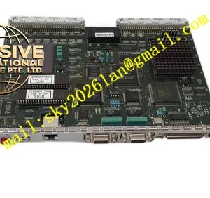
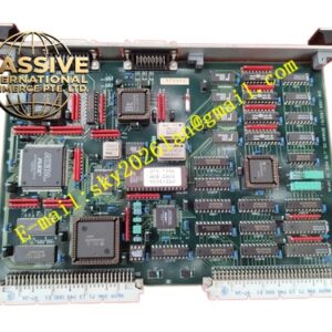
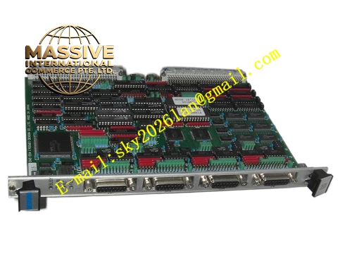
Densan DVE‑534(9226B)
Technical Specifications: Bus specification: VME ANSI/IEEE 1014 Form factor: 6U single‑slot VME plug‑in module Signal type: isolated digital input Field rated signal voltage: 24 VDC Galvanic isolation withstand voltage: 1500 VAC between field side and VME bus side Operating temperature: 0 ℃‑55 ℃ Storage temperature: -40 ℃‑85 ℃ Relative humidity: 5%‑95% non‑condensing Protection grade: IP20 Backplane connector: DIN 41612 J1
Functional Features: Multi‑channel galvanically isolated digital input channels. Per‑channel dedicated LED status indicator located on front panel. Input signal status latch function for transient signal capture. Hardware debounce circuit suppresses field contact bounce interference. Power‑on complete hardware self‑diagnosis. VME bus interrupt trigger when input signal state changes. Built‑in EMC filtering circuit for each input channel. All channel input status readable via VME bus register access.
Application Scenarios: Semiconductor equipment interlock signal monitoring, automated assembly line switch‑signal collection, industrial robot peripheral sensor signal acquisition, automated test equipment discrete signal cabinet, special‑purpose automated machinery VME control rack, production‑line safety interlock monitoring unit.
Performance Parameters: Input signal response time: less than 0.8 ms Input debounce filtering time: hardware configurable range Vibration resistance: 10 Hz‑150 Hz, 0.5 g Shock resistance: 10 g peak acceleration, 11 ms duration MTBF value: 205000 hours
Material Composition: Front‑panel adopts anti‑oxidation aluminum alloy. Main printed‑circuit‑board uses FR‑4 high‑Tg glass‑fiber epoxy substrate. Backplane connector contacts apply gold‑plated copper alloy. Isolation components adopt industrial‑grade optocoupler chips. Fastening hardware uses nickel‑plated steel.
Structural Features: Standard 6U single‑slot VME plug‑in structure. Metal front panel fitted with locking ejector handles and channel‑by‑channel LED indicators. Rear high‑density DIN connector connects VME rack backplane. Internal PCB strictly separates field signal isolation region and VME bus logic region. Every input channel is equipped with independent filtering and decoupling components. Ventilation slots on front panel realize passive convection cooling.
Working Principle: Field 24 VDC discrete input signals flow into on‑board optocoupler isolation circuit. Optocoupler converts field voltage signal into logic‑level digital signal for VME bus logic circuit. Hardware debounce circuit eliminates signal jitter generated by mechanical contact bounce. VME main controller reads input channel real‑time status by accessing hardware registers over VME backplane bus. When input signal state changes, board sends interrupt signal toward VME bus to notify host system. Front‑panel LED lamps directly reflect on‑off status of each field input channel.
Installation Requirements: Insert module to designated slot of 6U VME rack chassis, lock ejector handles and tighten front‑panel mounting screws. Guarantee adequate ventilation clearance inside cabinet. Apply shielded twisted‑pair cables for long‑distance field input signal wiring. Keep field signal cables away from high‑power drive cables. Disconnect rack total power supply before inserting or removing this circuit board. Execute static discharge before touching bare printed‑circuit‑board.
Precautions for Use: Prohibit input of high‑voltage AC signal onto field‑connected terminals. Wear anti‑static wristband during maintenance operations. Prevent dust accumulation on panel ventilation openings. Do not install in environment containing corrosive gas. Periodically inspect field wiring terminal tightness and connector contact condition.