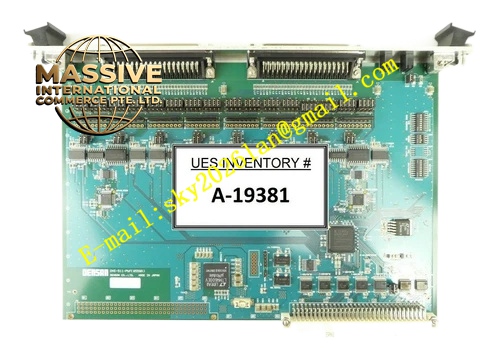
Description
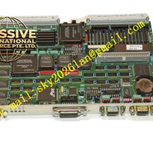
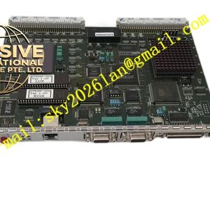
Densan DVE‑511
Technical Specifications: Bus standard: VME ANSI/IEEE 1014 Mechanical format: 6U single‑slot VME module Serial channel quantity: 8 independent asynchronous channels Interface selection: hardware jumper select RS‑232C, RS‑422, RS‑485 Baud rate coverage: 50 bps‑921600 bps Operating power: 7.4 W supplied from VME backplane 5 VDC and ±12 VDC Working ambient temperature: 0 ℃‑55 ℃ Storage temperature: -40 ℃‑85 ℃ Relative humidity: 5%‑95% non‑condensing Protection grade: IP20 Backplane connector: DIN 41612 J1
Functional Features: Eight independent full‑function serial communication channels. Jumper‑selectable physical interface for every channel. On‑board transmit and receive FIFO buffers to reduce CPU interrupt load. Front‑panel LED indicators for power supply, data transmit and receive activity. Built‑in surge suppression for serial port external circuits. Power‑on self‑diagnosis mechanism. VME bus interrupt generation upon data arrival or buffer full status. Support full‑duplex and half‑duplex transmission modes. All channel status accessible by reading VME‑mapped hardware registers. EMC filter components suppress industrial site electromagnetic interference.
Application Scenarios: Legacy semiconductor production equipment control cabinet, automated test system multi‑serial‑port expansion, industrial machinery serial instrument connection, retrofitted old VME‑based automation racks, special‑purpose industrial test benches, factory process monitoring equipment with numerous serial sensors.
Performance Parameters: Maximum baud rate per serial channel: 921600 bps FIFO buffer capacity per channel: 256 bytes transmit, 256 bytes receive Vibration resistance: 10 Hz‑150 Hz, 0.5 g Shock resistance: 10 g peak acceleration, 11 ms pulse duration MTBF value: 188000 hours under standard cabinet cooling
Material Composition: Front panel material is surface‑treated aluminum alloy. Main circuit substrate is FR‑4 glass‑fiber epoxy printed circuit board. Backplane connector pins adopt gold‑plated copper alloy. Integrated logic and serial transceiver components adopt industrial temperature grade. Solder material uses traditional tin‑lead solder alloy. Fastening components are nickel‑plated steel material.
Structural Features: 6U single‑slot VME plug‑in board mechanical construction. Metal front panel equipped with locking ejector handles and multi‑group LED indicator lamps. Rear DIN 41612 high‑density connector mates with VME rack backplane. Internal PCB divides VME bus logic zone, serial transceiver zone and power filter zone. Differential signal wiring area reserved for RS‑422 and RS‑485 signal paths. Multiple decoupling capacitors distributed across circuit board. On‑board jumper banks for channel interface setting. Ventilation cutouts on front panel support passive heat dissipation.
Working Principle: After system power‑on, DVE‑511 completes hardware initialization and self‑check procedure. VME host controller writes configuration register values over VME backplane bus to define baud rate, data bit, parity setting and physical interface mode for each serial channel. Incoming serial signals from field equipment enter on‑board transceiver chips, converted into parallel data and stored inside receive FIFO buffer. When data amount reaches threshold, interrupt signal is sent to VME bus so host CPU can read buffered data. For outbound transmission, host writes parallel data to transmit FIFO, hardware converts parallel data to serial bit stream and outputs to external serial devices. LED lamps on front panel reflect real‑time communication activity status. Fault and channel status information can be obtained by reading VME bus registers.
Installation Requirements: Insert DVE‑511 module into designated empty slot of 6U VME rack chassis. Engage ejector locking mechanism and tighten front‑panel mounting screws to achieve reliable backplane connector contact. Ensure sufficient air circulation space inside control cabinet for heat dissipation. Deploy shielded twisted‑pair cables for all external serial wiring. Maintain physical separation between serial signal cables and high‑voltage power cables. Cut off rack main power supply before plugging in or pulling out this board. Perform static elimination before touching bare printed‑circuit‑board surface. Do not adjust on‑board jumpers while system is powered.