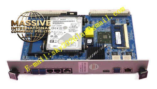
Description
Densan DVE‑P7447‑50A
Technical Specifications: Bus standard: VME ANSI/IEEE 1014 Mechanical format: 6U single‑slot VME plug‑in module Power supply: 5 VDC, ±12 VDC input from VME backplane Operating temperature: 0 ℃‑55 ℃ Storage temperature: -40 ℃‑85 ℃ Relative humidity: 5%‑95% non‑condensing Protection grade: IP20 Backplane connector: DIN 41612 J1/J2
Functional Features: High‑speed bidirectional data‑bridge function between dedicated processor interface and VME bus. On‑board large‑capacity data‑buffer memory for high‑throughput data transmission. Front‑panel LED indicators for power, data‑transmit activity and fault‑alarm status. Hardware‑based data‑integrity checking mechanism. Complete power‑on hardware self‑diagnosis routine. Support VME bus interrupt signal output. Built‑in EMC filtering circuit suppresses industrial‑site electromagnetic interference.
Application Scenarios: Semiconductor‑equipment dedicated‑processor VME control rack, industrial embedded‑processor expansion interface unit, automated‑test‑equipment high‑speed data‑transmission cabinet, special‑purpose industrial‑machinery VME‑based hybrid‑control system.
Performance Parameters: Maximum bidirectional data throughput depends on processor‑interface configuration Vibration resistance: 10 Hz‑150 Hz, 0.5 g Shock resistance: 10 g peak acceleration, 11 ms pulse duration MTBF value: 185000 hours
Material Composition: Front‑panel uses anti‑oxidation aluminum‑alloy material. Main printed‑circuit‑board adopts FR‑4 high‑Tg glass‑fiber epoxy substrate. Backplane‑connector contacts apply gold‑plated copper‑alloy. Data‑buffer memory and interface logic chips adopt industrial‑grade components. Fastening hardware uses nickel‑plated steel.
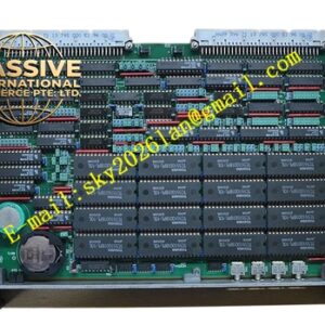
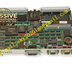
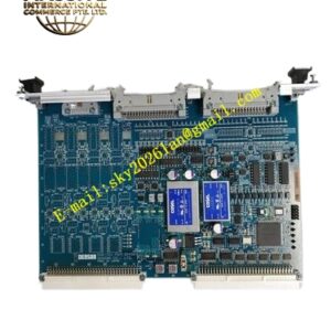
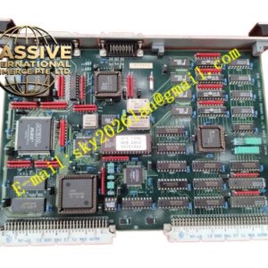
Structural Features: 6U single‑slot VME plug‑in mechanical construction. Metal front panel equipped with locking ejector handles and LED status indicators. Rear multi‑row high‑density gold‑plated DIN connector connects VME rack backplane. Internal PCB strictly divides VME bus interface region, data‑buffer region and external‑processor signal‑interface region. Mass decoupling capacitors distributed across printed‑circuit‑board to stabilize power‑supply quality. Ventilation openings reserved for passive convection heat dissipation.
Working Principle: After rack power‑on, DVE‑P7447‑50A completes hardware initialization and power‑on self‑test. It establishes physical‑layer connection with external dedicated processor hardware. It receives data stream from processor side, stores data inside on‑board buffer memory, then forwards data toward target VME bus module through VME backplane bus. In reverse direction, it receives data sent by VME I/O modules and transmits data to external processor unit. Hardware integrity check mechanism monitors data transmission quality. Front‑panel LED lamps reflect real‑time working status of this interface board. Fault information can be retrieved from VME‑accessible hardware registers.
Installation Requirements: Insert module fully into designated slot of 6U VME rack chassis. Lock ejector handles and tighten front‑panel mounting screws to guarantee reliable backplane‑connector contact. Maintain sufficient air‑circulation space inside cabinet for heat dissipation. Use high‑quality shielded cables for external‑processor‑interface wiring. Separate interface signal cables away from high‑power drive cables. Disconnect rack total power supply before inserting or removing this board. Perform static‑discharge operation before touching bare printed‑circuit‑board surface.
Precautions for Use: Do not feed over‑rated voltage onto external‑processor‑interface terminals. Wear anti‑static wristband in all maintenance procedures. Keep ventilation openings free of dust accumulation. Avoid installation location with corrosive gas and conductive dust. Periodically inspect screw fastening condition and connector aging status.