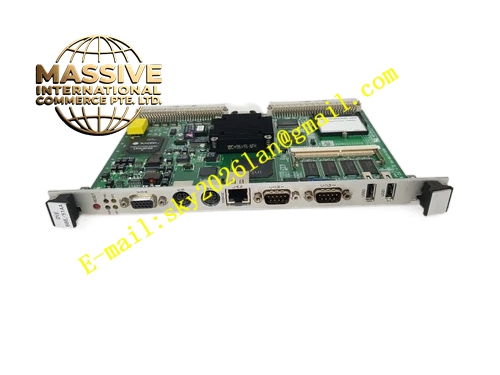
Description
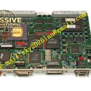
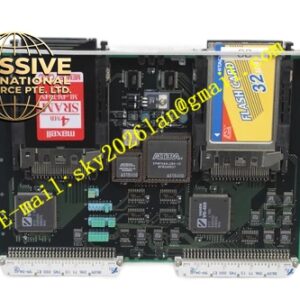
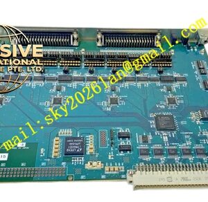
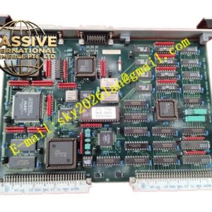
Densan DVE686‑51AA
Technical Specifications: Bus standard: VME64 Operating supply voltage: 5 VDC, ±12 VDC Backplane connector type: DIN 41612 Operating ambient temperature: 0 ℃ to 55 ℃ Storage temperature range: -40 ℃ to 85 ℃ Relative humidity: 5% to 95% non‑condensing Mounting form: 6U VME plug‑in module Protection grade: IP20
Functional Features: High‑speed VME bus data transmission capability. Multi‑channel parallel signal acquisition and processing circuit. On‑board large‑capacity flash memory for parameter storage. Hardware watchdog circuit for automatic fault reset. Front‑panel LED status indicators for power, running and fault alarm. Support interrupt signal output toward VME backplane. Built‑in EMC filtering circuit to resist workshop electromagnetic noise. Complete hardware diagnostic function for self‑check upon power‑on.
Application Scenarios: Semiconductor wafer processing equipment control cabinet, precision robotic motion control system, automated optical inspection equipment, large‑scale factory automation VME rack system, electronic component manufacturing production line, industrial real‑time process monitoring unit.
Performance Parameters: VME bus data throughput: up to 40 MB/s Watchdog trigger time: configurable from 10 ms to 2 seconds Vibration resistance: 10 Hz‑150 Hz, 0.5 g Shock resistance: 10 g peak acceleration, 11 ms duration MTBF value: 196000 hours under standard cabinet working environment
Material Composition: Module front panel uses aluminum alloy with anti‑oxidation surface treatment. Main printed circuit board uses FR‑4 high‑Tg glass‑fiber epoxy substrate. Backplane connector pins adopt gold‑plated copper alloy. On‑board electronic components are full industrial‑grade specification. Fixing hardware adopts nickel‑plated steel.
Structural Features: Standard 6U VME plug‑in structure. Metal front panel equipped with status LED indicators and locking handles. Rear multi‑row high‑density gold‑plated connector connects VME backplane bus. Internal PCB implements strict zoning for analog signal circuit, digital logic circuit and power circuit. Multiple groups of decoupling capacitors distributed across the whole board for signal stability. Ventilation openings are reserved on metal panel for passive heat dissipation.
Working Principle: After power‑on, the board executes complete hardware self‑diagnosis procedure. It receives configuration commands and transmits real‑time operating data via VME backplane bus. On‑board logic circuit processes input signals from external equipment and generates control output signals. Hardware watchdog continuously monitors program running status. When program exception occurs, watchdog triggers hardware reset to restore normal board operation. All operating status information is fed back through front‑panel LED indicators and VME bus registers.
Installation Requirements: Insert module into designated slot of standard 6U VME rack chassis. Tighten front‑panel locking screws to guarantee reliable connection with backplane. Maintain sufficient air circulation space around rack for heat dissipation. Separate signal cables and high‑power drive cables inside cabinet. Disconnect total rack power supply before plugging or removing this board. Complete static discharge operation before touching circuit board.
Precautions for Use: Strictly avoid overvoltage input toward board power pins. Wear anti‑static wristband during all maintenance and replacement operations. Keep ventilation openings free of dust accumulation. Do not install in environments containing corrosive gas or conductive dust. Regularly inspect front‑panel screw fastening condition and connector aging status. Back up all configuration parameters before board replacement.