Description
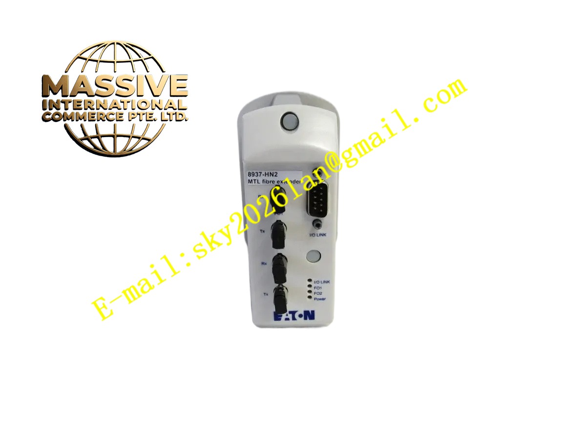
Eaton 8937-HN2
Technical Specifications
- Product Type: Auxiliary control relay module
- Rated Control Voltage: 24VDC / 120VAC / 240VAC selectable
- Contact Configuration: Multiple SPDT auxiliary contacts
- Contact Rated Current: 10 A resistive load
- Mechanical Endurance: 10 million operations
- Protection Rating: IP20
- Mounting Method: DIN rail mounting
- Operating Temperature: -25 °C to +70 °C
- Insulation Voltage: 2500 VAC dielectric strength
- Certification: UL, CSA, CE
Functional Features
- Multiple independent auxiliary contacts for status feedback and interlock circuits.
- High mechanical life cycle for frequent switching applications in power distribution panels.
- Built-in surge suppression circuit to reduce inductive load back EMF impact.
- Compact modular DIN rail design saves cabinet installation space.
- Visible mechanical position indicator shows contact status.
- Coil transient protection to extend coil service life.
- Compatible with Eaton series circuit breakers and motor starters.
- Low coil power consumption reduces heat generation inside cabinet.
- Finger-safe terminal design prevents accidental contact with live terminals.
- Quick release DIN rail latch for fast replacement.
Application Scenarios
- Low voltage switchgear breaker auxiliary status feedback
- Motor control center interlock and status signaling
- Building power distribution automation
- Industrial panel control circuit logic
- Generator switchgear auxiliary interlock
Material Composition
- Housing: Flame-retardant thermoplastic plastic
- Contact material: Silver alloy contact tips
- Coil: Copper magnet wire wound on laminated iron core
- Terminal block: Copper alloy screw terminals
- Moving armature: Laminated silicon steel sheet
- Insulation parts: Reinforced thermosetting plastic
Structural Characteristics
- Compact rectangular modular casing for DIN rail installation.
- Front window shows mechanical contact position indicator.
- Upper terminals for coil power wiring, lower terminals for auxiliary contact wiring.
- Internal electromagnetic coil and spring-driven contact armature assembly.
- Enclosed arc suppression chamber for contact arc quenching.
- Rear side equipped with spring locking clip for DIN rail fixation.
Working Principle When rated voltage applies to the coil, electromagnetic force pulls the armature to move. The mechanical linkage drives auxiliary contact sets to switch state between open and closed. When coil power cuts off, return spring resets armature and contacts back to original state. The auxiliary contacts carry low power control signals to reflect breaker or equipment mechanical status. The arc suppression chamber quenches electric arc generated during contact switching to protect contact surface.
Installation Requirements
- Mount horizontally on standard DIN rail inside control cabinet.
- Keep minimum side clearance between adjacent modules for heat dissipation.
- Use copper wire with proper cross-section for coil and contact wiring.
- Tighten terminal screws to specified torque value.
- Separate low-power control wiring from high-current power cables.
- Verify coil voltage matches supply voltage before power connection.
- Test contact switching action after wiring completion.
Usage Notes
- Do not exceed rated contact current and voltage rating.
- Do not use for switching heavy inductive loads without surge suppression.
- Keep cabinet environment dry and free from conductive dust.
- Check terminal screw tightness periodically under vibration environment.
- Do not apply overvoltage to coil beyond rated tolerance range.
- Replace unit if contact surface shows heavy burning or pitting.
- Store spare modules in dry ambient environment.