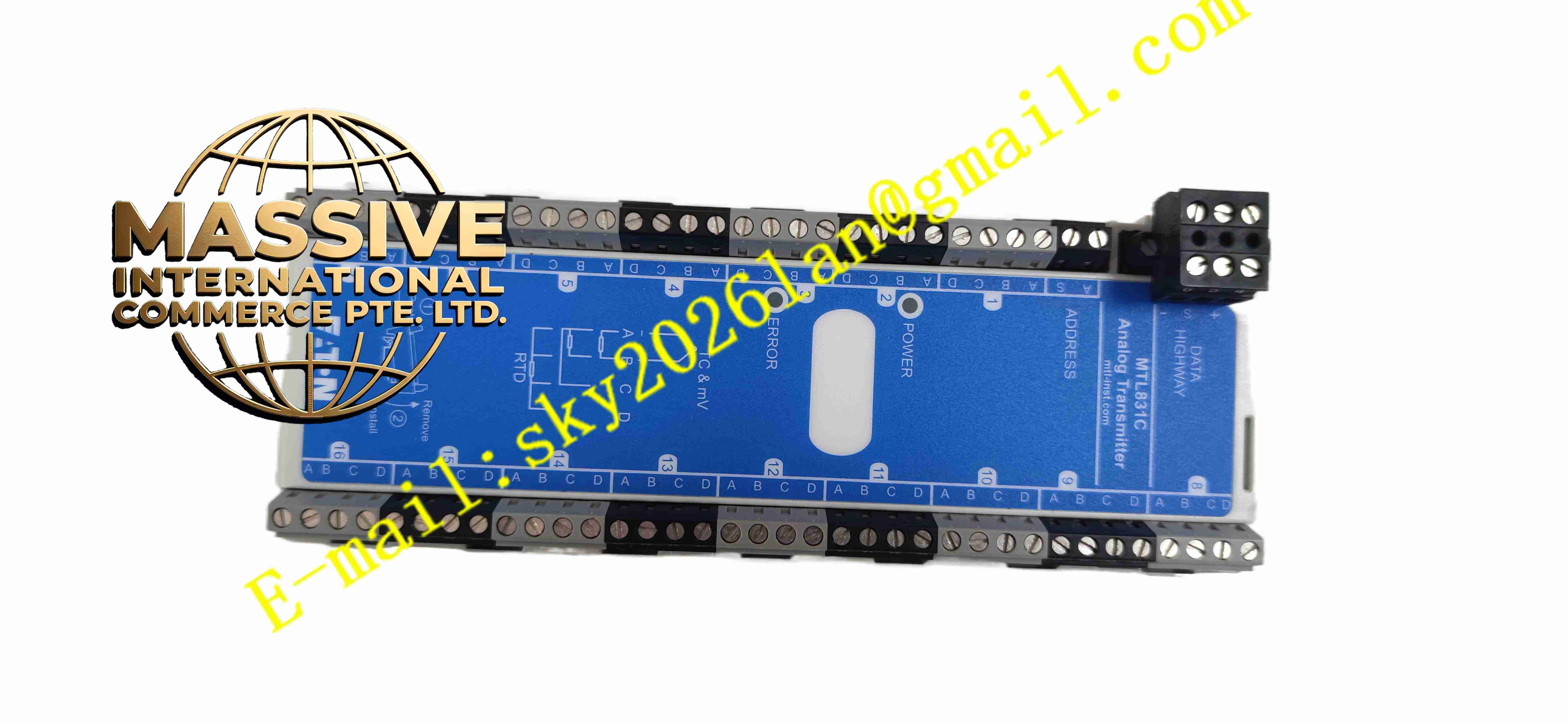
Description
Eaton MTL831C
Technical Specifications: Power supply: 19V DC ~ 30V DC Input channels: Up to 16 mixed signal input channels Supported input types: mV signal, thermocouple, 2/3/4 wire RTD, potentiometer mV measuring range: ±100mV Thermocouple types: B, C, E, J, K, N, R, S, T, XK RTD measurement range: -200℃ ~ +850℃ for Pt100 Accuracy at 21℃: Better of ±0.045% of input or ±20μV for mV signal Operating temperature: -20℃ ~ +60℃ Protection class: IP20 for module body Communication: RS485 multi-drop bus Certification: ATEX intrinsic safety certification
Functional Features: Supports mixed multi-type sensor input on different channels. High precision signal sampling and linear compensation for temperature sensors. Digital bus transmission reduces signal attenuation and field interference. Intrinsic safety circuit limits energy to prevent explosion in hazardous zone. Channel fault detection, open circuit and short circuit alarm function. Multiple MTL831C devices can be connected on one bus network. Software channel configuration without hardware jumper modification.
Application Scenarios: Oil & gas refineries, chemical processing plants, pharmaceutical factories, petrochemical pipelines, offshore platforms, coal chemical facilities and any explosion hazardous industrial sites requiring temperature and analog signal acquisition.
Performance Parameters: Temperature drift of measurement accuracy: ±0.0008% of input per ℃ Maximum bus quantity: Multiple MTL831C connect to one MTL838C receiver Response speed: Fast sampling cycle for all 16 channels Fault diagnosis: Detect sensor wire break and short circuit
Material Composition: Module housing: Flame retardant ABS plastic. PCB substrate: FR4 glass fiber epoxy board. Isolation components: Intrinsic safety barrier resistors, capacitors and optocouplers. Terminal blocks: PA66 flame retardant plastic with copper alloy conductors.
Structural Features: Compact rectangular DIN rail mounting module. Front terminal blocks for field sensor wiring. LED indicators for power status and communication activity. Internal circuit divided into safe side and hazardous side isolation zones. Standard DIN rail clip for quick installation and removal.
Working Principle: Field sensors installed in hazardous area connect to MTL831C input terminals. The module’s intrinsic safety barrier limits the maximum energy delivered to field side to meet explosion protection requirement. High precision analog front end samples sensor signal, converts analog value to digital data. The digital data is packaged and transmitted over RS485 bus to MTL838C receiver in safe area. Receiver converts digital data into Modbus signal for PLC or DCS system reading.
Installation Requirements: Mount on DIN rail inside safe area control cabinet. Separate hazardous field wiring and safe area wiring, different cable trays. Use intrinsically safe certified cables for field sensor wiring. Connect protective earth ground to designated grounding terminal. Set device address before bus network commissioning. Ensure the entity parameters match connected field sensors.
Usage Notes: Only use certified intrinsically safe field sensors matching entity parameters. Do not replace internal components arbitrarily in hazardous environment. Cut off power supply before wiring work. Avoid overvoltage applied to input terminals. Regularly inspect terminal tightness and cable insulation integrity. Do not use the module beyond certified temperature and voltage range.