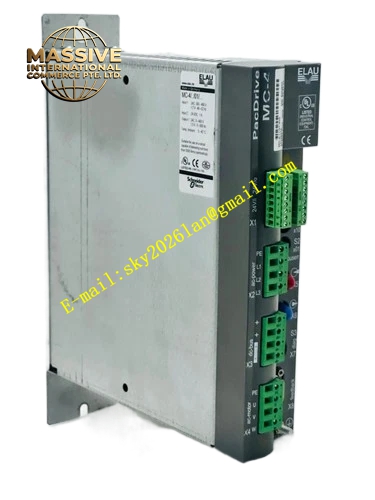
Description
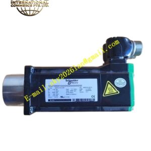
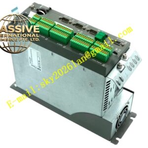
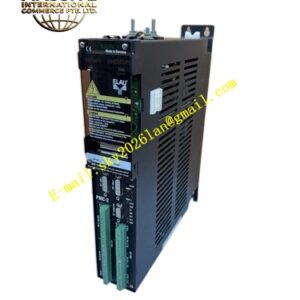
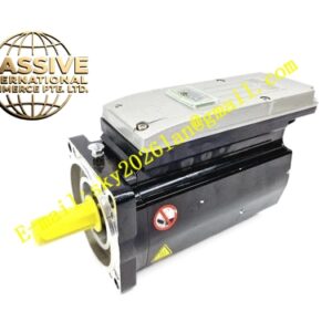
ELAU MC4-11-01-400
Technical Specifications Main Power Input: 3‑phase AC 380‑480 V, 48‑62 Hz Control Power Supply: DC24 V, 1 A continuous consumption Rated Output Current: 1.5 A continuous Peak Output Current: 3 A Output Frequency Range: 0‑600 Hz Communication Interface: SERCOS fiber‑optic interface Protection Class: IP20 Operating Ambient Temperature: 0 °C to +55 °C Storage Temperature:‑25 °C to +70 °C Mounting Method: Cabinet wall‑mount installation Cooling Mode: Natural convection cooling
Functional Features Full‑digital three‑loop closed‑loop control for current, speed and position. Electronic motor nameplate identification completes automatic motor configuration without manual parameter input. SERCOS fiber‑optic communication delivers strong electromagnetic interference immunity and microsecond‑level synchronization accuracy across multi‑axis groups. Comprehensive built‑in protection functions include over‑current, over‑voltage, under‑voltage, over‑temperature, motor phase loss and bus communication fault detection. Internal non‑volatile memory stores fault history codes and runtime diagnostic logs. Hardware inverter‑enable safety input supports safe torque‑off function. Modular compact mechanical layout reduces cabinet installation space occupation. LED status indicator array displays real‑time hardware operating state and alarm information.
Application Scenarios Light‑duty single‑axis positioning stations of packaging machinery; label registration auxiliary axes; small‑size rotary indexing mechanisms; low‑power auxiliary motion axes for printing and converting equipment.
Performance Parameters Short‑term overload capacity reaches 250 % of continuous rated output current. Steady‑state speed control accuracy achieves ±0.01 %. SERCOS bus synchronization jitter stays below 1 microsecond. Fault event data retains inside non‑volatile memory after power‑off cycle. Deterministic control cycle maintains stable performance under full‑load operating status.
Material Composition Galvanized steel sheet metal housing, FR‑4 multilayer high‑speed printed circuit board, IPM intelligent power module, fiber‑optic transceiver chipset, non‑volatile flash memory chips, plug‑in screw terminal blocks, SMD LED indicator components, varistor surge suppression components.
Structural Characteristics Vertical wall‑mount housing form factor. Upper section accommodates SERCOS fiber‑optic ports and LED status indicator array. Middle section carries main power input terminals, motor power output terminals and DC‑bus link terminals. Lower section arranges DC24 V control‑power terminals, safety input terminals and digital signal terminals. Metal identification nameplate permanently prints complete part number MC4‑11‑01‑400. Internal circuit layout implements partition shielding design to suppress electromagnetic interference.
Working Principle Three‑phase industrial AC mains passes internal rectifier circuit and converts into stable DC‑bus voltage. Main‑control processor receives position‑speed‑torque command frames transmitted over SERCOS fiber‑optic bus from upper‑level PacDrive motion controller. Control algorithm generates PWM drive signals to trigger IPM power module, output three‑phase variable‑frequency AC power to connected servo motor. Motor feedback signals return back to drive unit to close current‑speed‑position control loops. Built‑in monitoring circuit continuously samples hardware temperature, bus voltage and output current values. When abnormal operating condition appears, power output gets immediately locked and corresponding fault code stores inside on‑board memory.
Installation Requirements Mount drive unit vertically on solid metal cabinet wall. Reserve sufficient clearance on upper and lower sides to guarantee natural convection airflow. Strictly follow specified torque values when tightening power‑circuit screw terminals. Use shielded motor power cables and shielded feedback cables for motor connection. Physically separate low‑signal fiber‑optic and signal wiring from high‑voltage power cables. Connect protective‑earth terminal reliably to cabinet protective ground busbar. Comply with SERCOS fiber‑optic minimum bending‑radius specifications during cable routing.
Usage Notes Hot‑plugging SERCOS fiber‑optic connectors under powered condition is prohibited. Complete full backup of system configuration parameters before hardware replacement work. Wear anti‑static wrist strap when performing internal circuit maintenance service. Prevent hardware exposure to conductive dust, oil mist and corrosive vapors. Operate strictly within defined ambient‑temperature operating range.