Description
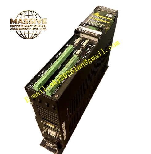
ELAU MM‑15‑10‑MM1510
Technical Specifications: Operating supply voltage 5 VDC supplied through system back‑plane, non‑volatile flash storage capacity 1 MB, compatible with PMC‑2 series main controller rack, gold‑plated back‑plane contact pins, protection rating IP20, module dimension 52 mm × 23 mm × 11 mm, net weight 0.10 kg, operating ambient temperature range 0 °C to +55 °C.
Functional Features: Non‑volatile storage retains user program and configuration data after complete power‑off, stores electronic cam profile, motion parameter table and historical fault event log, supports hot‑swap replacement under system running state, data read‑write protection mechanism prevents accidental data loss, fast data loading when controller powers‑on, supports program backup and restore function.
Application Scenarios: PMC‑2 motion control system program storage, packaging machinery multi‑cam curve data preservation, textile automation equipment parameter storage, printing converting machine motion configuration saving, industrial special‑purpose machine control system data backup.
Performance Parameters: Data retention period over 10 years without power supply, program loading time less than 200 ms at power‑on, maximum fault log storage quantity 2000 records, withstand vibration meets IEC 60068‑2‑6 standard, anti‑shock performance conforms to industrial control component specification.
Material Composition: Metal reinforced module outer frame, multi‑layer industrial‑grade printed circuit board, industrial‑grade flash memory chips, gold‑plated back‑plane contact pins, flame‑retardant insulating plastic structural components.
Structural Characteristics: Small‑size plug‑in card‑type module structure, special slot positioning design for PMC‑2 rack, gold‑plated contact pins connect with system back‑plane bus, no external wiring required, fully enclosed module shell prevents circuit board dust pollution.
Working Principle: After PMC‑2 main controller powers‑on, it reads application program, cam curve and system parameter data stored inside MM‑15‑10‑MM1510 module through back‑plane bus. User downloads compiled motion program into flash memory chip of memory module via programming software. All configuration data keeps stored inside flash chip when system powers‑off. Controller writes runtime fault event records into memory module during equipment operation.
Installation Requirements: Insert memory module into designated special slot inside PMC‑2 rack, push module in place completely, ensure full contact between gold‑plated pins and back‑plane connector; keep control cabinet internal ambient temperature within allowable range; avoid strong electromagnetic interference source nearby rack installation position.
Usage Notes: Do not extract module in program writing process, otherwise program data will get corrupted; back‑up program file before module replacement; prohibit module operation outside matched PMC‑2 rack system; avoid static electricity contact to circuit board components; replace module when flash chip read‑write error appears in system diagnostic information.