Description
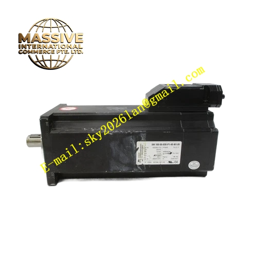
ELAU SM100‑50‑030‑P1‑45‑M1‑B1
Technical Specifications: Rated power 1.4 kW, rated speed 5000 rpm, maximum mechanical speed 5500 rpm, continuous stall torque 2.6 Nm, peak torque 10 Nm, rotor inertia 2.28 kg·cm², insulation class F (155 °C), protection class IP65, natural air cooling, B5 mounting flange size 100 mm, 19 mm flat‑key shaft, resolver M1 feedback interface, P1 power connector, built‑in B1 holding brake, total weight 7.7 kg, operating ambient temperature 0 °C‑40 °C.
Functional Features: Spring‑energized holding brake maintains static shaft position during power loss. Resolver feedback realizes outstanding anti‑interference capability under heavy electromagnetic noise field. Low‑inertia rotor structure achieves rapid speed variation and fast acceleration response. Internal PTC thermal sensor provides winding over‑temperature protection. High‑voltage winding design reduces phase current and cable power consumption. Fully compatible with ELAU PacDrive MC‑series servo drives.
Application Scenarios: Vertical lifting axes of packaging production machines, gantry automation handling systems, lifting‑type material transfer devices, printing press moving axes, automated assembly vertical positioning stations.
Performance Parameters: Brake static holding torque 8 Nm, brake coil rated voltage 24 V DC, CE and UL certified, three‑phase 400‑480 V AC power input.
Material Composition: Motor housing adopts high‑strength die‑cast aluminum alloy, stator core consists of stacked silicon‑steel sheets, rotor embeds neodymium‑iron‑boron rare‑earth permanent magnets, stator winding uses oxygen‑free copper wire, output shaft is quenched alloy steel, brake friction disc uses high‑wear‑resistant composite material, connector outer shell applies reinforced thermoplastic.
Structural Features: Standard B5 front‑flange mounting layout. Separate P1 power connector and resolver signal connector are installed on upper housing surface. Brake assembly locates at motor non‑drive rear end. Shaft‑end labyrinth sealing structure guarantees IP65 dust‑proof and water‑proof performance. PTC thermal sensing components embed inside stator winding.
Working Principle: Servo drive outputs three‑phase sinusoidal current to stator windings and generates rotating magnetic field. Magnetic field interaction between stator and rotor permanent magnet produces driving output torque. Resolver converts rotor mechanical angle into analog feedback signal and transmits to servo drive for closed‑loop speed and position regulation. Holding brake locks rotor shaft by spring force when 24 V DC brake power de‑energizes, and releases shaft immediately after rated voltage applies.
Installation Requirements: Fasten motor flange onto rigid low‑vibration metal mounting base. Keep coupling concentricity deviation below 0.05 mm. Route power cable and resolver feedback cable inside separated cable ducts. Complete reliable protective‑earth connection for motor housing. Reserve sufficient surrounding ventilation clearance for natural heat dissipation. Complete brake wiring strictly according to official pin‑assignment definition.
Usage Notes: Holding brake undertakes static‑holding duty only and cannot execute dynamic braking during motor running. Set servo drive feedback parameter to resolver mode. Keep operating environment non‑condensing with relative humidity 5‑85 %. Avoid corrosive gas and conductive dust contamination. Prohibit hammer striking motor output shaft in assembly procedure.