Description
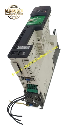
Emerson F1A493GU1
Technical Specifications: Control power supply: 24 VDC Signal sampling range: voltage and current analog signal Isolation voltage: 1500 VAC between power side and control side Operating temperature: 0 ℃ to 55 ℃ Storage temperature: -40 ℃ to 85 ℃ Relative humidity: 5% to 95% non-condensing
Functional Features: High-speed sampling of power circuit operating parameters. Closed-loop regulation of power output. Hardware over-current and over-temperature fault detection. Pulse signal generation for power switch components. Serial communication interface for status data upload. Built-in EEPROM stores configuration parameters and fault event records. LED indicators display board running and fault status.
Application Scenarios: Industrial power conversion unit control board, large motor drive control unit, power quality adjustment equipment, auxiliary power control device for power plant, industrial high-power rectifier equipment.
Performance Parameters: Signal sampling accuracy: ±0.2% full scale Control loop calculation cycle: less than 100 μs Vibration resistance: 10 Hz to 150 Hz, 0.5 g Shock resistance: 10 g peak acceleration, 11 ms duration MTBF value: 175000 hours
Material Composition: Board substrate: FR-4 glass fiber epoxy printed circuit board. Signal connectors: gold-plated copper alloy pins. Sampling components are high-precision industrial resistors and capacitors. Protection components are high-voltage transient suppression devices. Board fixing brackets use reinforced engineering plastic.
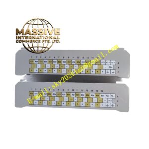
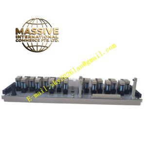
Structural Features: Flat rectangular printed circuit board structure. Multi-group pin connectors arranged on board edge for power, signal and communication wiring. Components arranged on top surface of PCB. Fixed installation holes at four corners of board. Isolation area layout separates high voltage power signal area and low voltage control signal area.
Working Principle: The board obtains 24 VDC control power. It samples voltage and current signals from power circuit through sampling circuit. Internal processor executes control algorithm according to set parameters. It generates drive pulse signal to control power semiconductor switching action. It continuously monitors temperature and current. When fault condition occurs, it immediately blocks drive pulse and records fault information.
Installation Requirements: Fix board on designated installation position of equipment chassis with screws. Keep isolation area layout unchanged. Reserve air circulation space around board. Separate high voltage wiring and low voltage signal wiring. Cut off all power supply before board installation or removal.
Precautions for Use: High voltage exists on matched power circuit, strictly follow lockout-tagout procedure. Wear anti-static wristband before touching PCB. Do not scratch copper foil and solder pad on board. Regularly check connector tightness. Replace board immediately if sampling signal drift exceeds specification.