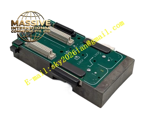
Description
Emerson KJ4001X1-BA3I
Technical Specifications
- Processor: High reliability industrial safety processor
- Onboard Memory: Non-volatile memory for safety logic program storage
- LocalBus Interface: DeltaV SIS LocalBus backplane communication
- Redundancy Synchronization Interface: Dedicated redundancy synchronization port
- LocalBus Supply: 12VDC
- Operating Ambient Temperature: 0℃ ~ 60℃
- Storage Temperature: -40℃ ~ 85℃
- Relative Humidity: 5% ~ 95%, non-condensing
- Protection Grade: IP20
- Installation Type: DeltaV SIS rack plug-in module
- Built-in comprehensive self-diagnosis function
- Front panel LED indicators for running, fault and redundancy status
Functional Features High-reliability safety processor executes safety interlock and emergency shutdown control logic continuously. Non-volatile memory keeps safety control program and configuration data without power supply. Dedicated redundancy synchronization circuit realizes real-time data synchronization between primary and standby safety controllers. Comprehensive self-diagnosis circuit checks processor, memory, communication interface and internal power circuit continuously. Front-panel LED indicators display module running state, fault alarm and redundancy working status. Plug-in rack mechanical design supports hot swap under non-critical safety operating conditions. Dual redundant controller configuration supports seamless bumpless switchover.
Application Scenarios DeltaV SIS safety control cabinets in chemical plants, oil refineries, natural gas processing facilities and offshore platforms. It serves as core processing unit of safety instrumented system to execute emergency shutdown, fire and gas safety interlock control logic.
Performance Parameters Safety processor runs safety logic program stably within full working temperature range. Self-diagnostic circuit captures internal hardware fault rapidly. Redundancy synchronization channel maintains real-time data consistency between primary and standby controllers. SIS LocalBus ensures reliable bidirectional data transmission between safety controller and SIS I/O modules.
Material Composition Flame-retardant engineering plastic front panel. Multi-layer flame-retardant glass-fiber epoxy PCB. Safety processor chip, non-volatile memory chips, redundancy synchronization circuit and LED indicators. Gold-plated copper alloy backplane connector. Metal shielding components for anti-electromagnetic interference.
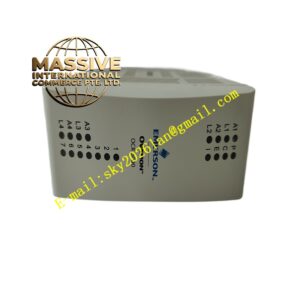
Structural Features Standard plug-in card matching DeltaV SIS rack slot. Front panel equipped with running LED, fault LED and redundancy status LED indicators. Guide rails and mechanical latch lock module firmly inside safety rack. Rear gold-plated connector mates with DeltaV SIS rack backplane. Dedicated external redundancy synchronization port for redundant controller pair connection. Internal metal shielding reduces electromagnetic interference impact.
Working Principle The safety controller obtains working power from SIS rack backplane LocalBus. It collects safety measurement and discrete status data from SIS I/O modules via SIS LocalBus. Safety processor executes pre-downloaded safety interlock and emergency shutdown logic. After logic calculation, controller sends safety control commands to SIS digital and analog output modules. Redundancy synchronization circuit transmits real-time operation data to standby controller for data consistency. On-board self-diagnosis circuit continuously detects internal hardware faults. When fault occurs, module generates safety fault alarm and triggers redundant switchover automatically.
Installation Requirements Insert module along rack guide rail into designated DeltaV SIS rack slot and lock mechanical latch. Connect redundancy synchronization cable between primary and standby safety controller modules. Reserve air circulation space around module for heat dissipation. Download safety control logic program and complete hardware configuration in DeltaV safety engineering workstation after hardware installation.
Precautions for Use Take anti-static protective measures during module handling. Do not touch gold-plated connector pins directly by bare hands. Inspect redundancy synchronization cable and connector condition regularly. Do not apply overvoltage to communication terminals. Do not disassemble module housing.