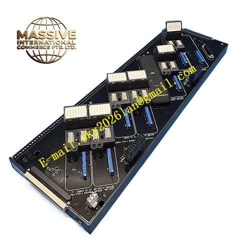
Description
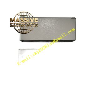
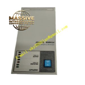
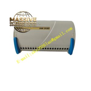
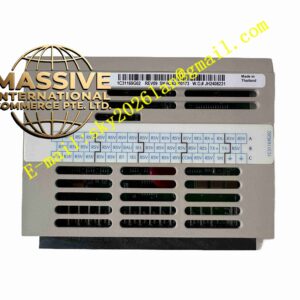
Emerson KJ4002X1‑BA1
Technical Specifications
- Slot Quantity: 8 independent I/O‑module mounting slots
- LocalBus Operating Voltage: 12.6 VDC, maximum total load‑current 8 A
- Bussed Field‑Power Rating: maximum 30 VDC, aggregated 6.5 A across all slots
- Operating Ambient Temperature: ‑40 °C ~ +70 °C
- Storage Temperature: ‑50 °C ~ +85 °C
- Relative Humidity: 5 %‑95 %, non‑condensing
- Airborne Contaminant Classification: ISA‑S71.04‑1985 Class G3
- Protection Class: IP20
- Shock Resistance: 10 g half‑sine wave pulse, 11 ms duration
- Vibration Resistance: 1 mm peak‑to‑peak amplitude for 2‑13.2 Hz; 0.7 g acceleration for 13.2‑150 Hz
- Installation Mode: vertical cabinet‑mounting, left‑side orientation
- Compatibility: all DeltaV M‑Series I/O‑modules and corresponding rotary‑keyed terminal‑blocks
- Cascading Restriction: total cumulative LocalBus carrier cascading length shall not exceed 6.5 metersEmerson
Functional Features Vertical‑left‑oriented 8‑slot layout optimizes cabinet‑space utilization for narrow‑width cabinet body. Internal printed‑circuit traces distribute LocalBus communication signal and 12.6 VDC system‑power to each of eight module‑slots. Internal trace network transmits bussed field‑power supply to matched front‑mounted terminal‑block assemblies. Integrated metal EMI‑shielding structure suppresses external industrial electromagnetic‑noise interference. Hardware slot‑position coding supports automatic slot‑recognition function of DeltaV system‑software. Rotary mechanical anti‑mismatch keying prevents installation of incompatible terminal‑block hardware. Passive‑hardware architecture without active electronic‑components improves long‑term operational‑reliability. Individual I/O‑modules support hot‑swap replacement operation under energized carrier‑state. Blank filler‑covers install onto permanently unused slots to preserve electromagnetic‑shielding integrity of carrier assembly. Carrier hardware itself does not permit hot‑swap disconnection, must de‑energize LocalBus power before removalEmerson.
Application Scenarios Petrochemical refineries, chemical‑processing plants and thermal‑power‑plant control cabinets with narrow‑width cabinet‑body structure. Adopts vertical‑left‑side installation layout, assembles large‑quantity M‑Series analog and discrete I/O‑modules, completes field‑transmitter, valve, limit‑switch and solenoid‑actuator signal‑input‑output processing.
Performance Parameters LocalBus signal‑transmission maintains stable performance under full‑slot loaded working‑condition. Internal power‑trace voltage‑drop stays within strict tolerance range under maximum rated‑current‑load. Integrated EMI‑shielding structure restrains radiated electromagnetic‑noise intrusion into I/O‑signal path. Mechanical‑clamping force of module‑connector keeps stable for long‑term cabinet‑vibration environment. Supports continuous 7×24‑hour non‑stop operation inside industrial‑cabinet environment.
Material Composition High‑strength reinforced‑plastic carrier housing with integrated metal EMI‑shielding bar. Multilayer glass‑epoxy printed‑circuit board with heavy‑copper power‑carrying traces. Gold‑plated female edge‑connectors for mating with M‑Series I/O‑module plug‑in contacts. Stainless‑steel hardware components for vertical cabinet‑mounting and mechanical‑locking. Flame‑retardant plastic‑material conforms to industrial fire‑safety‑specification.
Structural Characteristics Vertical‑orientation modular structure for left‑side cabinet‑installation. Front‑side arranges eight vertical‑direction module‑insertion openings, each equipped with independent mechanical‑locking latch. Internal metal‑shielding bar bonds with cabinet‑protective‑ground potential for noise‑suppression. Rear‑side integrated multi‑pin‑connector interfaces with upstream LocalBus power‑supply and communication‑source hardware. Special‑designed mounting‑bracket position adapts vertical left‑side cabinet‑fixing requirement. Vertical‑direction arranged passive‑convection air‑gaps reserve heat‑dissipation space for inserted I/O‑modules.
Working Principle Upstream DeltaV power‑supply hardware delivers 12.6 VDC LocalBus power and LocalBus communication‑signal to KJ4002X1‑BA1 rear‑side multi‑pin‑connector. Internal printed‑circuit traces distribute power and communication‑bus‑signal separately toward each of eight vertically‑arranged front‑facing module‑slots. When M‑Series I/O‑modules plug‑into corresponding slots, gold‑plated edge‑contacts complete electrical‑connection between carrier‑backplane‑circuit and I/O‑module‑internal‑circuit. Bussed field‑power‑signal routes through carrier‑internal traces and transmits outward to matched front‑mounted terminal‑blocks. Field‑wiring connects onto terminal‑blocks and further links to I/O‑module‑channel‑circuits. This vertical‑type carrier executes no signal‑computation or data‑processing task internally, works purely as passive interconnection‑medium for power‑distribution and signal‑routing.
Installation Requirements Fix carrier assembly onto left‑side vertical mounting‑position inside ventilated DeltaV control‑cabinet by using dedicated vertical‑mounting‑bracket. Complete cabinet‑protective‑ground‑connection for carrier‑integrated metal‑shielding‑bar, grounding‑resistance stays under 4 Ohm. Carry‑out carrier‑wiring‑work under full‑power‑off‑condition for LocalBus power‑supply and field‑power‑circuits. Connect upstream LocalBus power‑source and communication‑cable onto carrier rear‑side multi‑pin‑connector. Install matched rotary‑keyed terminal‑blocks onto carrier‑front‑positions before inserting I/O‑modules. Fit blank filler‑covers for all permanently unused module‑slots. Total cumulative‑length of cascaded LocalBus carrier‑assemblies cannot exceed 6.5 metersEmerson.
Usage Precautions Do not exceed rated 8 A LocalBus total‑current limit and 6.5 A bussed field‑power‑current‑limit. Ensure cabinet‑ventilation‑channel remains unobstructed, avoid heat‑accumulation around vertical‑mounted carrier‑assembly. Verify rotary‑key‑setting‑matching‑relationship between carrier‑terminal‑block‑combination and inserted I/O‑module‑hardware. Only individual I/O‑modules support hot‑swap‑operation; carrier‑assembly itself must be fully de‑energized before disconnection or removalEmerson. For hazardous classified Zone 2 installation‑scenarios, strictly follow DeltaV M‑Series Zone 2 installation‑manual‑document. Carrier‑assembly cannot be disassembled, no user‑serviceable internal‑components exist.