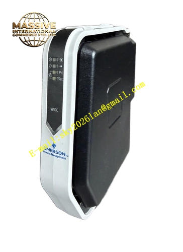
Description
Technical Specifications: Rated operating voltage: 24 VDC Isolation voltage: 1500 VAC between field side and control side Operating temperature range: 0 ℃ to 60 ℃ Storage temperature range: -40 ℃ to 85 ℃ Relative humidity: 5% to 95% non-condensing Mounting method: 35 mm DIN rail installation Protection grade: IP20
Functional Features: Supports hot replacement of DeltaV S series I/O electronic modules. Built-in overvoltage and surge protection for each signal channel. Screw terminal design ensures reliable cable connection. Front panel LED lights indicate power, channel and fault status. Backplane connector transmits power and signal data to I/O module. EMC filtering circuit eliminates external electromagnetic noise. Built-in electronic ID chip for automatic system identification. Independent short-circuit protection for each field loop.
Application Scenarios: Refinery DCS control cabinet, chemical continuous production automation system, power plant boiler auxiliary control, mining process control cabinet, food and beverage production control, waste incineration process control system.
Performance Parameters: Terminal contact resistance: less than 10 milliohm Vibration resistance: 10 Hz to 150 Hz, 0.5 g Shock resistance: 10 g peak acceleration, 11 ms duration MTBF value: 209000 hours under standard cabinet environment
Material Composition: Module housing uses UL94-V0 flame-retardant engineering thermoplastic. Internal PCB adopts FR-4 glass fiber epoxy substrate. Terminal contact parts and screws are nickel-plated brass. Backplane connector pins use gold-plated copper alloy. DIN rail fixing clip is stainless steel.
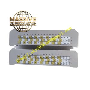
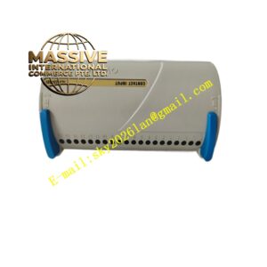
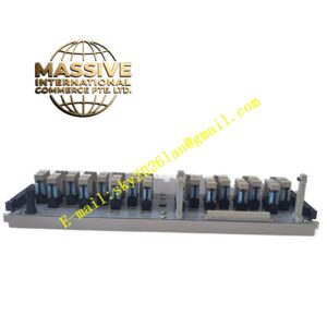
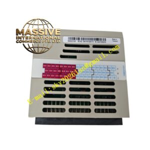
Structural Features: DIN rail plug-in mounting structure. Front panel integrates signal terminals and LED status indicators. Top locking mechanism fastens the I/O electronic module. Rear multi-pin gold-plated connector connects backplane power and bus. Internal partition separates high interference field circuit and low-voltage control circuit. Vent slots are reserved for passive heat dissipation.
Working Principle: Field sensor and actuator cables access front panel screw terminals. Raw signals pass through internal surge protection and filtering circuit. Signals transmit to the matched I/O electronic module through rear backplane connector. The terminal base keeps field wiring connected when the I/O module is pulled out for replacement. The diagnostic circuit continuously detects open circuit and short-circuit faults of field wiring.
Installation Requirements: Install the terminal base on standard 35 mm DIN rail inside control cabinet. Keep enough vertical space above and below the module for heat dissipation. Route analog signals with shielded twisted pair cables. Separate low-voltage signal cables and high-power cables. Tighten terminal screws according to torque specification. Disconnect field power before wiring modification.
Precautions for Use: Verify signal voltage level before wiring. Wear anti-static wristband during maintenance work. Inspect terminal tightness regularly. Keep ventilation slots free of dust accumulation. Do not install in environments with conductive dust.