Description
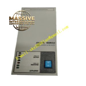
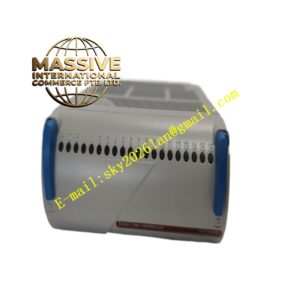
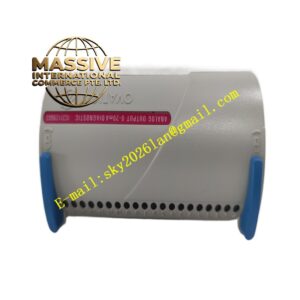
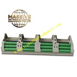
Emerson VE4033S2B1
Technical Specifications: Power supply: 24 VDC. Channel isolation: Galvanic isolation between field and system side. Operating temperature: 0 ℃ ~ 60 ℃. Storage temperature: -40 ℃ ~ 85 ℃. Humidity: 5% to 95% non-condensing. Compliance standard: IEC 61010, IEC 61131.
Functional Features: Supports field transmitter loop power supply. Each channel has independent overcurrent protection. Equipped with LED status indicators for power and channel fault. Supports hot insertion and extraction of matched I/O cards. Built-in EMI filter reduces electromagnetic interference from field equipment. It provides test jacks for signal measurement during maintenance.
Application Scenarios: Chemical process control, oil and gas pipeline monitoring, refining plant automation, pharmaceutical batch control, food and beverage process control, power plant auxiliary control system.
Performance Parameters: Surge withstand capability: 2kV common mode surge. Maximum per channel current: 20mA for analog loop. Vibration resistance: 10-150Hz, 1g. Shock resistance: 15g peak, 11ms. MTBF: 230000 hours.
Material Composition: Base housing: UL94-V0 flame retardant plastic. Terminal screw: Brass with nickel plating. PCB substrate: FR4 epoxy glass board. Filter and protection components sealed with epoxy compound. Mounting spring clip: Stainless steel.
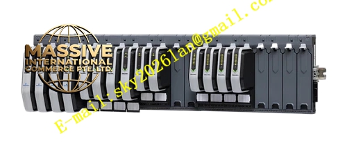
Structural Features: 35mm DIN rail snap mounting design. Front panel has LED indicator window and channel marking area. Card socket is on the top surface for I/O card insertion. Wiring terminals are arranged on the front lower side. Built-in positioning structure prevents wrong card installation. The shell has ventilation slots for passive heat dissipation.
Working Principle: Field signals are connected to screw terminals. Signals go through EMI filter and surge protection circuit, then transfer to the DeltaV I/O card installed on the base. The card converts field signals into digital data for controller. The terminal block provides 24V loop power for 2-wire transmitters on site. Fault detection circuit feeds back channel abnormal state to controller.
Installation Requirements: Mount on standard 35mm DIN rail inside control cabinet. Reserve 20mm space for ventilation. Separate analog signal cables and power cables in different wiring channels. Torque for terminal screws is 0.5 N·m to 0.7 N·m. Complete wiring before powering on the system. Keep away from high-power frequency converter cables.
Precautions for Use: Do not use in explosive hazardous areas without corresponding explosion-proof certification. Do not apply voltage exceeding rated value to signal terminals. Perform static protection when handling the module. Regularly clean dust on the surface of the terminal base. Replace the terminal base immediately if the shell has cracks or burn marks.