Description
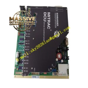
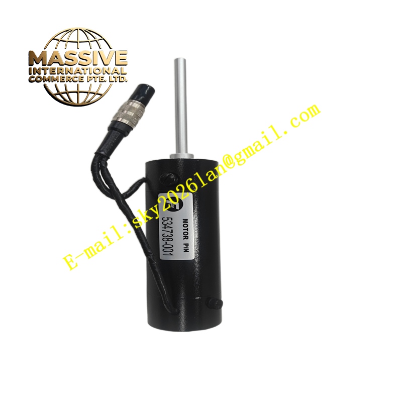
FiFe 534738-001
Technical Specifications Incremental digital pulse output; high resolution angle sampling; industrial grade vibration resistance; differential signal output; matched mounting flange and shaft interface; wide working temperature range.
Functional Features Captures real-time angular displacement and rotation speed of the mechanical shaft. Outputs differential pulse signals to enhance anti-interference ability in industrial environments. Supports direction discrimination through phase difference of pulse channels. Transmits position feedback data to servo controllers to realize closed-loop motion regulation.
Application Scenarios Packaging machinery, automated production lines, CNC machine tools, material handling servo axes and other precision motion control equipment.
Performance Parameters High angular resolution; low phase jitter of output pulses; stable signal output under continuous rotation; strong resistance to mechanical vibration and shock.
Material Composition Outer housing is die-cast aluminum alloy; internal optical code disc uses high-transmittance optical glass; light receiving and emitting components are semiconductor optoelectronic chips; shaft bearing is precision miniature rolling bearing; wiring terminal parts are nickel-plated copper.
Structural Characteristics Compact cylindrical housing; central rotating shaft or hollow shaft structure; mounting flange with fixing holes; cable outlet for signal wiring; internal optical reading head and code disc assembly sealed inside the shell.
Working Principle The optical code disc rotates synchronously with the mechanical shaft. Light from the light source passes through the slits on the code disc and is received by photoelectric sensors. The photoelectric components convert light changes into pulse electrical signals. The controller calculates rotation speed and angular position according to the quantity and phase sequence of pulses.
Installation Requirements Align the encoder shaft and the driving mechanical shaft to ensure coaxiality. Fasten the encoder flange to the fixed support with standard fasteners. Use shielded twisted-pair cables for signal wiring. Test pulse output and direction recognition after installation.
Precautions for Use Do not apply excessive axial and radial impact load on the encoder shaft. Prevent metal chips and cutting fluid from entering the encoder shell. Avoid exceeding the maximum allowable rotating speed of the encoder.