Description
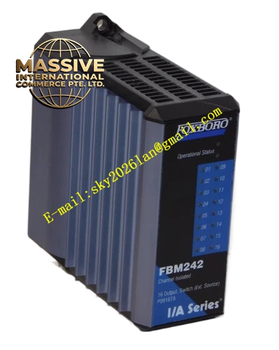
Foxboro FBM242
Technical Specifications
- Output Type: 16 x Form C (SPDT) Relay Contacts.
- Contact Rating: Typically 2A @ 250V AC / 30V DC.
- Isolation: Full channel-to-channel and channel-to-system isolation.
- Bus Interface: Redundant 2 Mbps module fieldbus.
Functional Features
- High Isolation: Each relay contact is isolated, allowing switching of different voltage levels and preventing cross-circuit interference.
- Status Indication: Individual LEDs for each channel provide visual confirmation of output state.
- Safe State: Outputs can be configured to fail-safe (de-energize) or fail-last upon module or bus failure.
- Hot-Swappable: Supports online replacement to minimize downtime.
Application Scenarios
Used for equipment start/stop control, safety interlock outputs, alarm annunciation, and driving motor control circuitry in process and manufacturing environments.
Performance Parameters
- Operate Time: < 10ms typical.
- Release Time: < 10ms typical.
- Electrical Life: Hundreds of thousands of operations at rated load.
- Mechanical Life: Tens of millions of operations.
Material Composition
Industrial-grade relays with silver-alloy contacts for arc resistance. Housed in a flame-retardant enclosure with a conformal-coated PCB.
Structural Characteristics
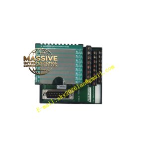
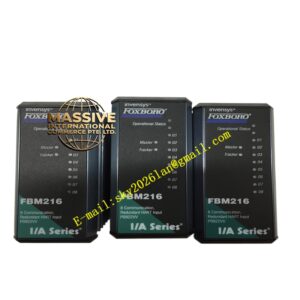
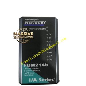
Standard FBM form factor. Front panel has 16 LEDs and a module label. Rear connector provides access to all 16 relay contacts (Common, NO, NC).
Working Principle
The module receives discrete output commands from the DCS controller over the fieldbus. Its internal driver circuit energizes the corresponding relay coil, closing or opening the mechanical contacts to control the external load circuit.
Installation Requirements
Must be connected to an FTA that provides appropriate wiring for relay outputs and, if necessary, external snubber circuits for inductive loads.
Usage Precautions
- Never exceed the voltage or current rating of the relay contacts.
- For inductive loads (solenoids, contactors), always install external RC snubbers or flyback diodes to suppress arcing and protect the contacts.
- Before replacing the module, force all outputs to a safe state via the DCS to prevent unintended equipment operation.