Description
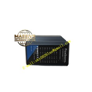
Foxboro P0961EF
Technical Specifications
- Architecture: 32-bit RISC processor with hardware-accelerated floating-point unit.
- Control Execution: Typical scan times of less than 100ms for complex loops.
- I/O Capacity: Supports extensive I/O expansion via fieldbus modules.
- Network: Dual redundant Ethernet ports for control network connectivity.
Functional Features
- Deterministic Performance: Separates control execution from communication tasks to guarantee consistent scan times.
- Advanced Control: Supports PID loops, sequence control, and safety interlocks with millisecond precision.
- Redundancy: Hot standby capability with automatic failover to ensure maximum uptime.
- Self-Diagnostics: Continuous monitoring of processor health, memory integrity, and communication status.
Application Scenarios
Critical for large petrochemical complexes, power generation turbine control, and any continuous process where system availability directly impacts production output and safety.
Performance Parameters
- Failover Time: Less than 100ms seamless transition during redundancy switchover.
- MTBF: Greater than 150,000 hours.
- Certifications: UL, cULus, CE, ATEX, SIL 3.
Material Composition
High-reliability industrial components selected for long-term stability. PCBs feature multi-layer design for signal integrity and thermal management.
Structural Characteristics
Standard Eurocard form factor with front-panel LEDs indicating Primary/Secondary status, run state, and error conditions. Includes a battery compartment for memory retention.
Working Principle
Executes the user-defined control algorithm in a cyclic scan. It reads inputs from the I/O subsystem, performs mathematical and logical operations, updates outputs, and synchronizes its state with the redundant partner processor via a dedicated sync link.
Installation Requirements
Must be installed in a designated controller slot. Redundant processors require a dedicated synchronization cable connection. Ensure the cabinet grounding meets industrial standards.
Usage Precautions
- Replace the memory battery according to the maintenance schedule to prevent program loss.
- Avoid forcing modifications to safety-critical parameters while the system is in RUN mode.
- Monitor system logs after any redundancy switchover to identify the root cause.