Description
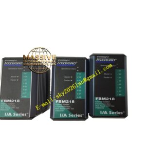
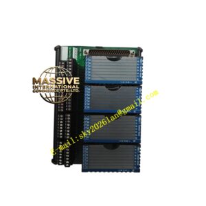
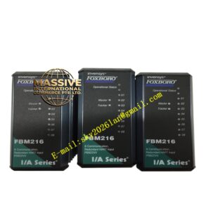
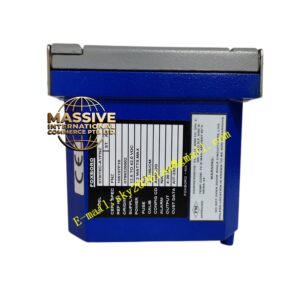
Foxboro SPU 232 .2 029.366 817
Technical Specifications
- Product type: Analog signal processing unit
- Input: 4 to 20 mA or 10 to 50 mA
- Output: 4 to 20 mA / pneumatic or current
- Isolation: Channel isolation
- Accuracy: High stability
- Supply: Loop or external
- Operating temperature: 0 °C to +60 °C
- Storage temperature: -20 °C to +70 °C
- Humidity: 5 % to 95 %, non-condensing
- Protection: IP20
- Installation: Rack / panel
- Adjustment: Zero and span potentiometers
- LEDs: Power and fault
Functional Features
- Analog signal isolation and conversion
- Signal amplification
- Zero and span adjustment
- Galvanic isolation
- Long term stability
- Industrial analog processing
- Rack mounting
- Channel fault indication
- Compatibility with Foxboro analog system
- Field proven design
Application Scenarios
- Refinery analog signal conditioning
- Chemical plant 4 to 20 mA isolation
- Foxboro control system signal interface
- Process control loop isolation
- Plant instrument signal conversion
Materials and Construction
- Housing: Coated metal
- PCB: FR4
- Isolation: Isolation amplifier
- Potentiometers: Multi-turn
- Terminals: Screw terminals
- LED: Status indicator
Structural Features
- Rectangular rack module
- Front panel zero and span potentiometers
- Rear screw terminals
- Internal isolation amplifier and power supply
- Metal shielding
- Rack mounting brackets
Working Principle Input analog signal enters conditioning circuit. Isolation amplifier separates input and output. Signal is scaled and offset by zero and span potentiometers. Output signal drives next control stage. Monitoring circuit indicates power or fault.
Installation Requirements
- Rack mount
- Wire input and output signals
- Connect supply
- Grounding
- Temperature 0 °C to +60 °C
- Adjust zero and span after power-up
- Keep signal cables shielded
- Separate input and output wiring
Precautions
- Do not exceed input signal range
- Potentiometers set by qualified technician
- Store spares in dry packaging
- Periodically recalibrate zero and span
- Avoid vibration on potentiometer
- Isolate wiring before service
- Keep cabinet dry