Description
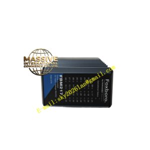
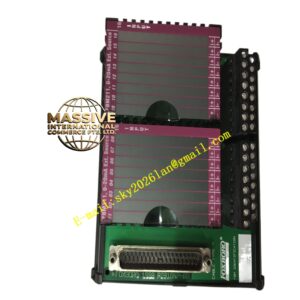
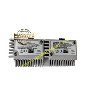
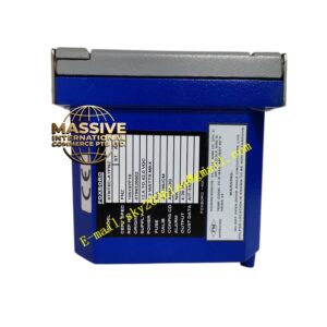
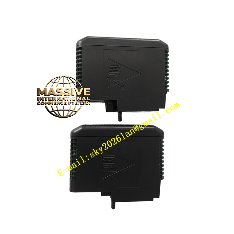
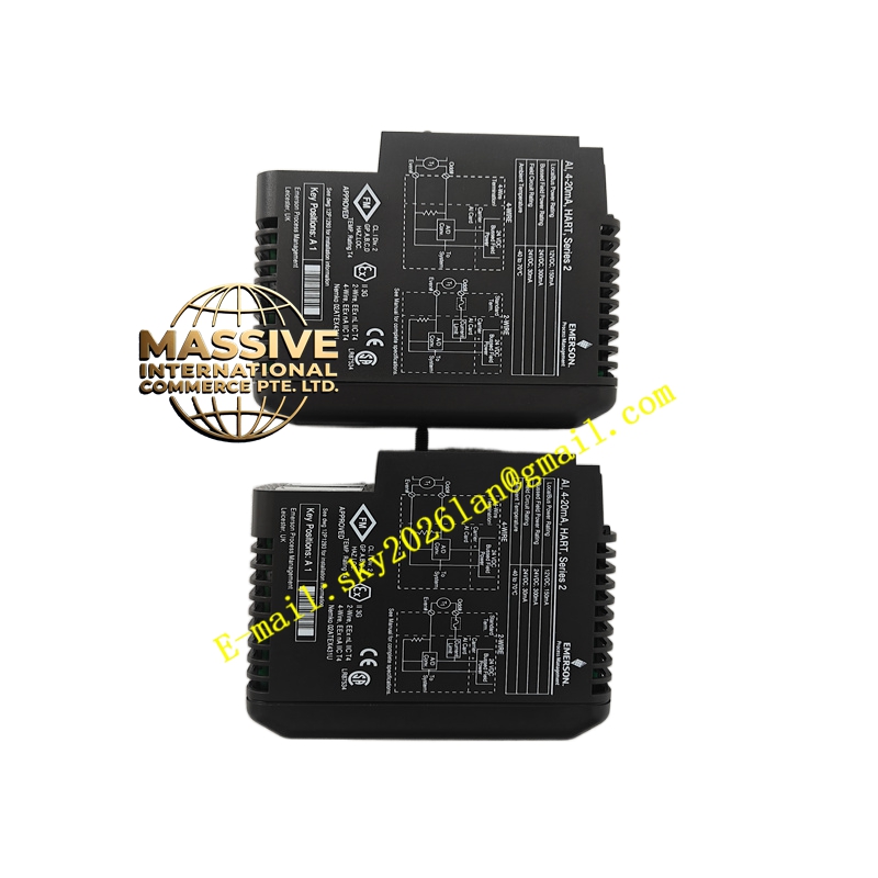
Foxboro VE4003S2B1
Technical Specifications:
- Type: Power Supply / Interface Module
- Input Voltage: Typically 85–265 V AC or 125 V DC (depending on exact configuration)
- Output Voltage: 24 V DC (regulated)
- Output Current: Supports various current loads (e.g., 10 A, 20 A depending on system configuration)
- Efficiency: High efficiency switching design
- Protection: Overcurrent, overvoltage, and short-circuit protection
- Operating Temperature: 0 °C to +60 °C
- Mounting: Rack or panel mount
Functional Features:
- Converts standard AC or DC input to regulated DC output
- Provides monitoring and status feedback of the power supply health
- Supports redundant operation when paired with a second unit
- LED indicators for power status, fault, and output health
- Low noise output suitable for sensitive analog circuits
Application Scenarios:
- Providing main power to I/A Series controller cabinets
- Powering Fieldbus Modules (FBMs) and processors
- Remote I/O cabinet power distribution
- Critical safety system power supplies
Performance Parameters:
- Low output ripple and noise
- Fast transient response to load changes
- High Mean Time Between Failures (MTBF)
Material and Structural Characteristics:
- Rugged metal chassis for heat dissipation
- Industrial-grade terminal blocks for input/output wiring
- Conformal coated internal electronics
Working Principle:
The module receives input power from the plant grid or UPS. Through a switching power supply topology, it converts the voltage to a tightly regulated 24 V DC. Internal regulation circuits adjust for load fluctuations, ensuring the output voltage remains constant. Protection circuits constantly monitor the output and cut power if a fault is detected to prevent damage.
Installation Requirements:
- Install in a well-ventilated area to prevent overheating
- Provide appropriate overcurrent protection at the source (upstream breakers)
- Ensure proper grounding of the chassis
- Connect output wiring to the distribution terminals securely
Usage Notes:
- Allow adequate clearance around the module for cooling airflow
- Check input voltage compatibility before installation
- Monitor status LEDs during operation to detect degrading performance
- Do not block the ventilation fins or slots